


251
Tel: 886.909 602 109 Email: [email protected]
www.salukitec.com
209
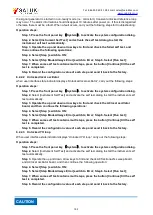
Signal generator (tested)
RF output
RF input
RF cable
Where,
Yi --- the frequency value measured for the i
th
measurement in Hz;
YP --- the average frequency measured for N measurements in Hz;
ti --- the time for the i
th
measurement in h;
tp --- the time of the N
th
measurement in h;
N --- the number of measurements.
Notes: Refer to 5.15.5 in GB/T 12114-2013 for test methods.
4) Harmonic parasitism
a) Test description
This test is used to verify whether the harmonic index of the signal generator is acceptable.
The harmonic is an integer multiple of the output frequency of the signal generator. During this
test, set the output power of the signal generator to a power level of +10 dBm or the maximum
indicated output power, manually adjust the output frequency within the index frequency range,
and test and find the worst point of the harmonics with the spectrum analyzer.
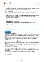
b) Test block diagram
Fig.7.4 Harmonic Test
c) Test equipment
Spectrum analyzer
1 set
RF coaxial cable
1 piece
d) Test procedures
Step 1. Power on and reset it, and warm it up for at least 30 minutes.
Step 2. Connect the device as shown in Fig.7.4.
Step 3. Set the signal generator under test to continuous wave mode, the power level to
+10 dBm or the maximum indicated power and RF on.
Step 4. Adjust the output frequency up to 33.5 GHz within the signal generator
specifications, test and find the worst point of the harmonics with the spectrum analyzer.
During the test, the signal generator shall be tested in segments (segment point at 3.2 GHz),
and the span of the spectrum analyzer shall be appropriately adjusted according to the change
of the output frequency of the signal generator. During the test, the frequency step of the signal
generator before the segment point is 10 MHz, and the frequency step after the segment point is
100 MHz.
Step 5. Record the test results.
Spectrum analyzer