36
Basic O
p
era
tion
Cha
p
ter
4
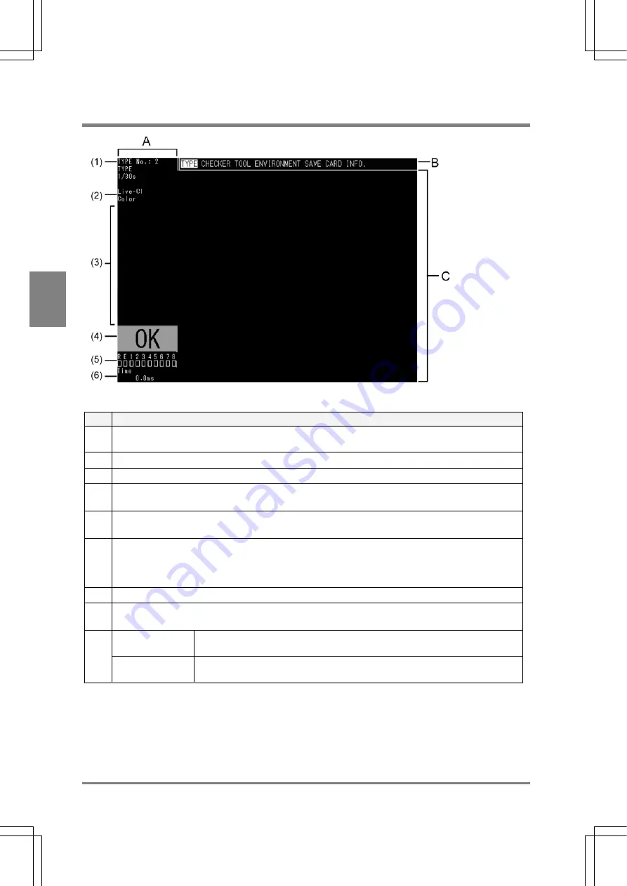
4.1 About Screen Monitor
No.
Description
A
Status display area:
Mainly displays the status of the AX40
(1)
TYPE number/ name and Shutter Speed that are currently selected
(2)
Image type that is currently displayed
(3) Message
area:
Displays messages, subwindows for checker setting, and results of the checker test
(4)
Total judgement result:
Displays "OK" in green if the judgement formula that is set to " Total Judgement" returns true.
(5)
Output status of signals:
If the signals listed below are output signals, the squares located under each signal are displayed in
green (only in RUN mode).
R: Ready signal / E: Error signal / 1-8: D1-D8 signals
(6)
Execution time (Unit: ms)
B Menu
Bar:
Menu bar displays the menu to set the inspection conditions and environment.
In RUN mode
Images, checker areas, inspection results, etc. are displayed according to the
settings in SETUP mode.
C
In SETUP mode
Images, checker areas, etc. are displayed. Each setting windows that are
selected from the menu bar are also displayed in this area.
Summary of Contents for Micro-Imagechecker AX40
Page 9: ...1 Names and Functions of Parts Chapter 1 Chapter 1 Names and Functions of Parts ...
Page 15: ...7 Installation and Wiring Chapter 2 Chapter 2 Installation and Wiring ...
Page 25: ...17 Input and Output Interface Ports Chapter 3 Chapter 3 Input and Output Interface Ports ...
Page 42: ......
Page 70: ......
Page 94: ...86 Setting Checkers Chapter 6 6 7 Gray Edge 6 7 1 Menu Options ...
Page 108: ...100 Setting Checkers Chapter 6 6 9 Smart Matching 6 9 1 Menu Options ...
Page 184: ......
Page 185: ...177 TOOL Chapter 8 Chapter 8 TOOL ...
Page 192: ......
Page 193: ...185 Environment Settings Chapter 9 Chapter 9 Environment Settings ...
Page 215: ...207 Chapter 10 Parallel Communication Chapter 10 Parallel Communication ...
Page 225: ...217 Chapter 11 RS232C Communication Chapter 11 RS232C Communication ...
Page 255: ...247 Chapter 12 Ethernet Communication Chapter 12 Ethernet Communication ...
Page 261: ...253 Chapter 13 Using a CF Card Chapter 13 Using a CF Card ...
Page 279: ...271 Chapter 15 Troubleshooting Chapter 15 Troubleshooting ...
Page 292: ...284 Specifications and Product Numbers Chapter 16 Camera Cable Keypad ...
Page 294: ...286 Specifications and Product Numbers Chapter 16 ANM88161 ANM88251 ANB842NL Unit mm ...


