272
Tr
oubleshootin
g
Cha
p
ter 1
5
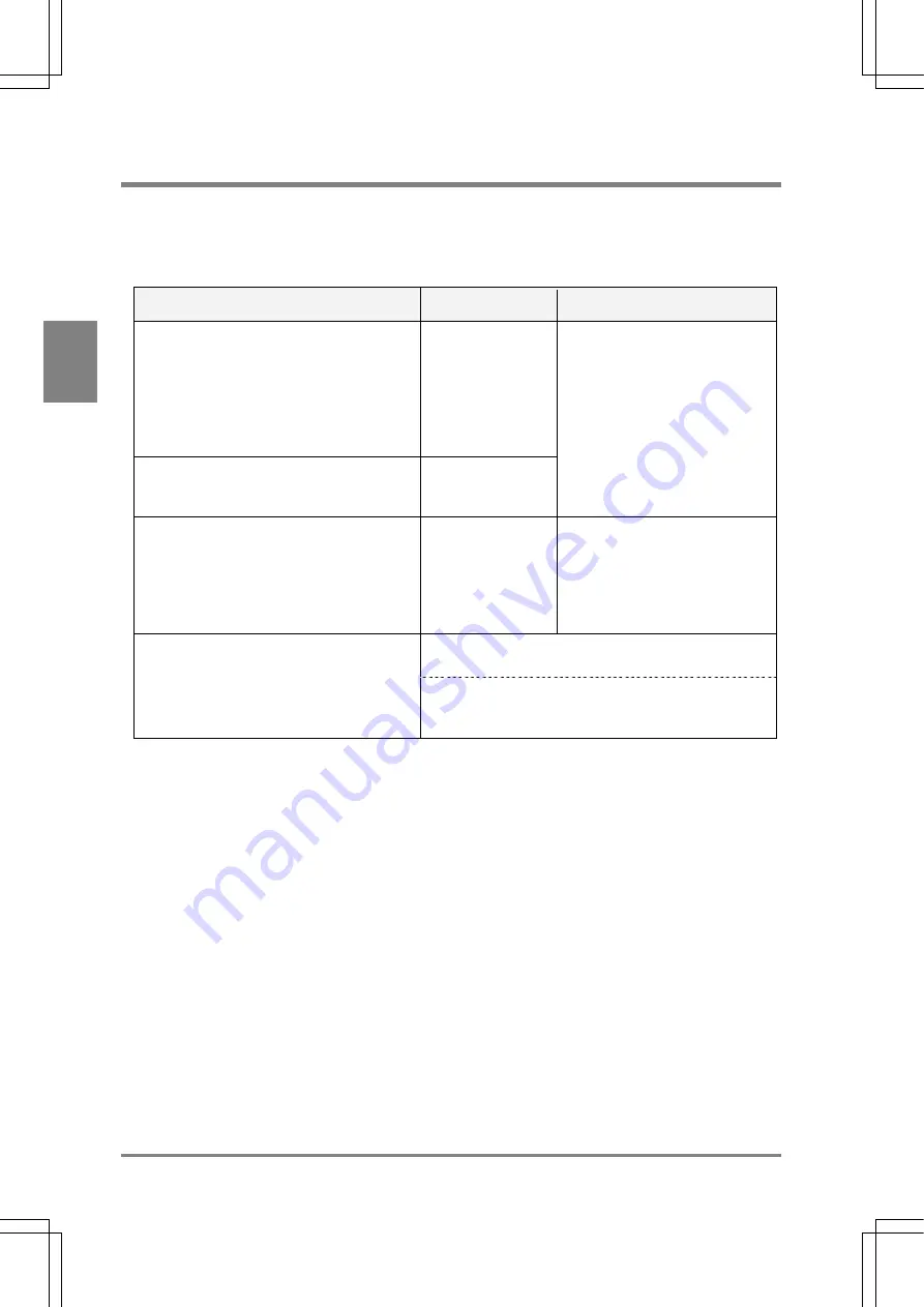
15.1 ERROR (Error) Signal Is Output
If ERROR (error) signal is output from the parallel terminal (the ERROR lamp of the AX40 is lit), the last
inspection was not properly executed or product type switch was not completed successfully. In this case,
please check the causes in the following table.
Problem: ERROR (error) signal is output during inspection
Cause
Relevant Function
Checking Procedure
Values exceeded the following ranges during
calculation
• Effective range of values during calculation
= -2147483648 to +2147483647 (- 2
31
- (2
31
-
1))
• Effective range of values during calculation of
operator “square root”
= 0 to 461239364
Arithmetic
calculation
Denominator became “0” when the division
that is specified as numeric calculation is
performed.
Arithmetic
calculation
“ER” is displayed in the calculation
result field.
Item that does not exist is quoted to the
Numeric calculation, Judgement, Statistics,
and Data Monitor windows. (If the quoted item
is deleted after being quoted.)
Arithmetic
calculation
Judgement output
Statistics
Data Monitor
• “ER” is displayed in the result
display area of Numeric
calculation, Judgement Output
and Statistics windows.
• “ER” is displayed in some cells in
Data Monitor window in RUN
mode.
The timeout setting value is altered, at the same time the
inspection time is changed.
Communication timeout error occurred. (Only if
inspection results are output through RS232C
communication by using the “computer link”
function.)
The timeout time setting value (default setting: 5000 ms)
can be changed by selecting “ENVIRONMENT”>”Serial
Settings”>”Output condition”.
Summary of Contents for Micro-Imagechecker AX40
Page 9: ...1 Names and Functions of Parts Chapter 1 Chapter 1 Names and Functions of Parts ...
Page 15: ...7 Installation and Wiring Chapter 2 Chapter 2 Installation and Wiring ...
Page 25: ...17 Input and Output Interface Ports Chapter 3 Chapter 3 Input and Output Interface Ports ...
Page 42: ......
Page 70: ......
Page 94: ...86 Setting Checkers Chapter 6 6 7 Gray Edge 6 7 1 Menu Options ...
Page 108: ...100 Setting Checkers Chapter 6 6 9 Smart Matching 6 9 1 Menu Options ...
Page 184: ......
Page 185: ...177 TOOL Chapter 8 Chapter 8 TOOL ...
Page 192: ......
Page 193: ...185 Environment Settings Chapter 9 Chapter 9 Environment Settings ...
Page 215: ...207 Chapter 10 Parallel Communication Chapter 10 Parallel Communication ...
Page 225: ...217 Chapter 11 RS232C Communication Chapter 11 RS232C Communication ...
Page 255: ...247 Chapter 12 Ethernet Communication Chapter 12 Ethernet Communication ...
Page 261: ...253 Chapter 13 Using a CF Card Chapter 13 Using a CF Card ...
Page 279: ...271 Chapter 15 Troubleshooting Chapter 15 Troubleshooting ...
Page 292: ...284 Specifications and Product Numbers Chapter 16 Camera Cable Keypad ...
Page 294: ...286 Specifications and Product Numbers Chapter 16 ANM88161 ANM88251 ANB842NL Unit mm ...


