


214
Parallel Communicatio
n
Cha
p
ter 1
0
10.2.5 Re-registering the Template
Overview
This is a function to update the template (base image) of the target checker by inputting signals from the
external device. When the signals are input, the template is updated based on the current image or
memory image. The number of the target checker to be re-registered and assigned to IN 1- 7 is specified
and the template is re-registered upon FCT2 signal input.
Target Checker
• Smart
Matching
• Contour
Matching
Re-register Mode
There are the following two modes for re-registration. For mode setting, select "Template Settings" from
the ENVIRONMENT menu.
• Setting
Position
Re-registering can be executed at the position of the preset template area. This mode is available if
the re-registration position of the object is the same as the setting position of the target checker.
• Adjustment
Position
If "Position Adjustment" is set to any other number than "0", this mode re-registers the template at the
adjustment position of the target checker after position adjustment or rotation adjustment is executed
and the target checker is adjusted. This mode will be available if the position of the re-registration
position of the object is not the same as the setting position of the target checker.
Area Display
This is a function to check the area to be re-registered on the monitor screen before re-registration after a
timing signal for executing re-registration and FCT2 signal are input. In this case, it is required to input
timing signals (or commands) to re-register twice. The area can be set by selecting "ENVIRONMENT" >
"Template Settings" from the menu bar.
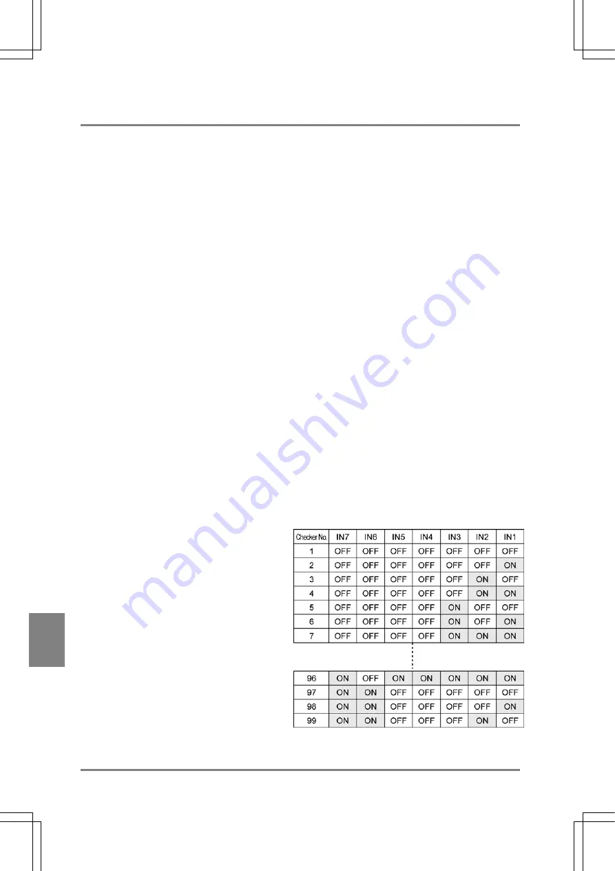
Specifying the Number of Checker To Register
Assign the number of the target checker you want to re-register to IN1 to 7 (7 bit). Specify the value
subtracted one from the actual product type number using binary data. Refer to the table shown below.
Summary of Contents for Micro-Imagechecker AX40
Page 9: ...1 Names and Functions of Parts Chapter 1 Chapter 1 Names and Functions of Parts ...
Page 15: ...7 Installation and Wiring Chapter 2 Chapter 2 Installation and Wiring ...
Page 25: ...17 Input and Output Interface Ports Chapter 3 Chapter 3 Input and Output Interface Ports ...
Page 42: ......
Page 70: ......
Page 94: ...86 Setting Checkers Chapter 6 6 7 Gray Edge 6 7 1 Menu Options ...
Page 108: ...100 Setting Checkers Chapter 6 6 9 Smart Matching 6 9 1 Menu Options ...
Page 184: ......
Page 185: ...177 TOOL Chapter 8 Chapter 8 TOOL ...
Page 192: ......
Page 193: ...185 Environment Settings Chapter 9 Chapter 9 Environment Settings ...
Page 215: ...207 Chapter 10 Parallel Communication Chapter 10 Parallel Communication ...
Page 225: ...217 Chapter 11 RS232C Communication Chapter 11 RS232C Communication ...
Page 255: ...247 Chapter 12 Ethernet Communication Chapter 12 Ethernet Communication ...
Page 261: ...253 Chapter 13 Using a CF Card Chapter 13 Using a CF Card ...
Page 279: ...271 Chapter 15 Troubleshooting Chapter 15 Troubleshooting ...
Page 292: ...284 Specifications and Product Numbers Chapter 16 Camera Cable Keypad ...
Page 294: ...286 Specifications and Product Numbers Chapter 16 ANM88161 ANM88251 ANB842NL Unit mm ...


