


194
Environment Settin
g
s
Cha
p
ter 9
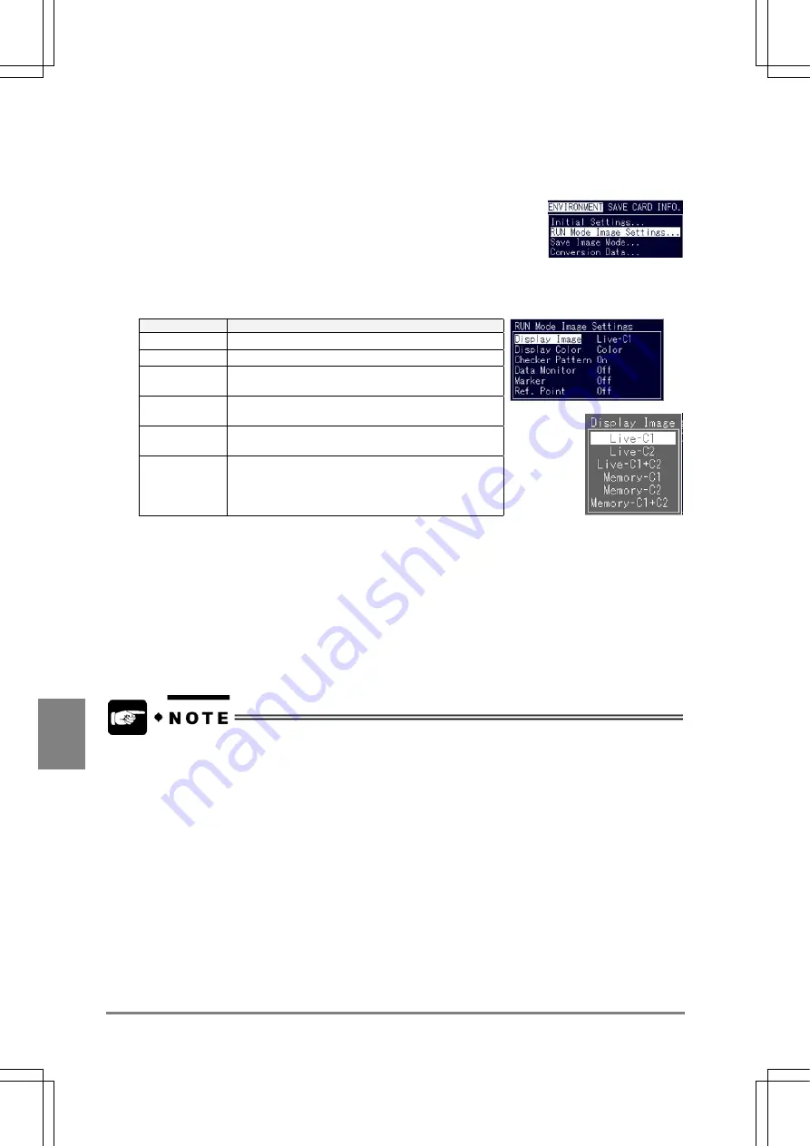
Switching the display image
1. Select “ENVIRONMENT” > “RUN Mode Image Settings”.
2. Select “Display Image”.
The Display Image menu is displayed.
Option
Image to be displayed
Live – C1
Live-image of Memory 1 (real-time image )
Live – C2
Live-image of Memory 2 (real-time image)
Live –2
display
Live-image of Memory 1, Memory 2 (real-time
image)
Memory C1
Memory-image of memory 1(still image for
inspection execution)
Memory C2
Memory-image of Memory 2 (still image for
inspection execution)
Memory2
display
Memory 1 and Memory 2 (still image for inspection
execution)
But, some parts of the images cannot be displayed depending on the preprocess setting and the display
color.
Example:
If Display Image = Gray, Memory 1 = Extraction, Memory 2 = Gray, Live-C2 or Memory-C2 is selectable for
switching display images.
3. Move the cursor to the image to change and press the ENTER key.
•
When you display a live image, the capture time of a live image is longer than that of a
memory image. At the time of inspection, it is advisable to display Memory C, Memory 2 or
Memory 2 display.
•
When inspection is executed with the Image Save function while the last saved image is
displayed," select Memory C1 or Memory 2 without fail.
Summary of Contents for Micro-Imagechecker AX40
Page 9: ...1 Names and Functions of Parts Chapter 1 Chapter 1 Names and Functions of Parts ...
Page 15: ...7 Installation and Wiring Chapter 2 Chapter 2 Installation and Wiring ...
Page 25: ...17 Input and Output Interface Ports Chapter 3 Chapter 3 Input and Output Interface Ports ...
Page 42: ......
Page 70: ......
Page 94: ...86 Setting Checkers Chapter 6 6 7 Gray Edge 6 7 1 Menu Options ...
Page 108: ...100 Setting Checkers Chapter 6 6 9 Smart Matching 6 9 1 Menu Options ...
Page 184: ......
Page 185: ...177 TOOL Chapter 8 Chapter 8 TOOL ...
Page 192: ......
Page 193: ...185 Environment Settings Chapter 9 Chapter 9 Environment Settings ...
Page 215: ...207 Chapter 10 Parallel Communication Chapter 10 Parallel Communication ...
Page 225: ...217 Chapter 11 RS232C Communication Chapter 11 RS232C Communication ...
Page 255: ...247 Chapter 12 Ethernet Communication Chapter 12 Ethernet Communication ...
Page 261: ...253 Chapter 13 Using a CF Card Chapter 13 Using a CF Card ...
Page 279: ...271 Chapter 15 Troubleshooting Chapter 15 Troubleshooting ...
Page 292: ...284 Specifications and Product Numbers Chapter 16 Camera Cable Keypad ...
Page 294: ...286 Specifications and Product Numbers Chapter 16 ANM88161 ANM88251 ANB842NL Unit mm ...


