242
RS232C Co
mmunication
Cha
p
ter 1
1
Note for the settings of PLC
• If the PLC does not allow data writing in RUN mode, the AX40 cannot write data, resulting in
communication error. If you use the PLC that can allow or forbid the AX40 to write data, set to allow
data writing.
• Mitsubishi A- and Q- series PLC
You can use only the special protocol for MELSEC A-series computer link unit, “Format 4”, to
communicate properly (Formats 1, 2, 3, 5 and the special protocol for Q series are not available).
Make sure that Format 4 is set in the PLC and the settings are valid. Also, set Sum checke to "Yes".
• Store “0” in the register for specifying communication format
Register for specifying communication format: D8120 (or D5420)
• If you use Allen-Bradley SLC500, configure the following settings:
- Duplicate Detect: OFF
- ACK Timeout (*20 ms): 20
- Control Line: NO HANDSHAKING
- Error Detect: BCC
- NAK Retries: 3
- ENQ Retries: 0
- Embedded Responses: AUTO DETECT
(Only integer registers are available.)
Connecting with PLC
Refer to page 28 for serial connection with the PLCs in previous page.
Be sure to connect the following parallel signals:
• Ready signal (RDY)
• Error signal (ERR)
Output Data
The data that can be output by using the computer link function is as follows:
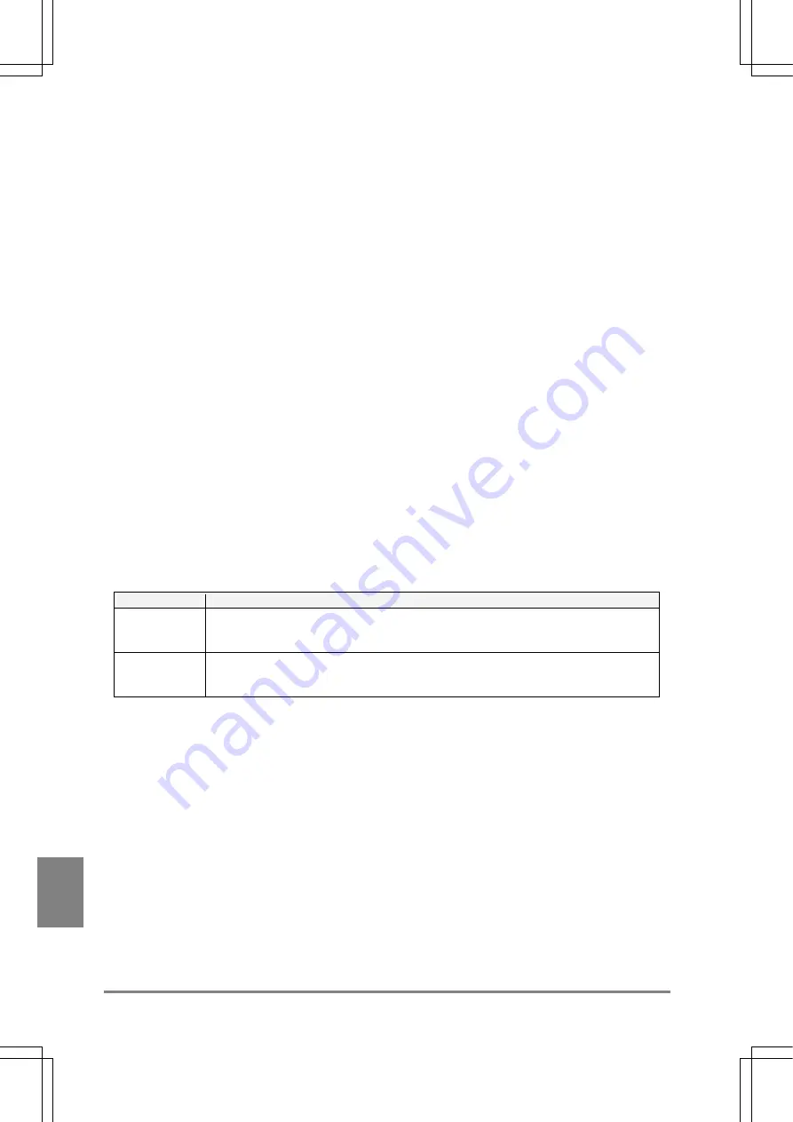
Data
Descriptions
Judgement
The results of numeric calculation assigned to "D1 to D8" for output under Judgement
regardless of "Output Data" settings. Judgement is output in digit unit. (Up to four results
are stored per data register.)
Data Monitor
The data of numerical calculation or statistics referred to Data Monitor which are set to
"Output". Starting from the leftmost cell in the first row, they are output from left to right
by rows through the last row. The output unit is 16-bit or 32-bit.
Summary of Contents for Micro-Imagechecker AX40
Page 9: ...1 Names and Functions of Parts Chapter 1 Chapter 1 Names and Functions of Parts ...
Page 15: ...7 Installation and Wiring Chapter 2 Chapter 2 Installation and Wiring ...
Page 25: ...17 Input and Output Interface Ports Chapter 3 Chapter 3 Input and Output Interface Ports ...
Page 42: ......
Page 70: ......
Page 94: ...86 Setting Checkers Chapter 6 6 7 Gray Edge 6 7 1 Menu Options ...
Page 108: ...100 Setting Checkers Chapter 6 6 9 Smart Matching 6 9 1 Menu Options ...
Page 184: ......
Page 185: ...177 TOOL Chapter 8 Chapter 8 TOOL ...
Page 192: ......
Page 193: ...185 Environment Settings Chapter 9 Chapter 9 Environment Settings ...
Page 215: ...207 Chapter 10 Parallel Communication Chapter 10 Parallel Communication ...
Page 225: ...217 Chapter 11 RS232C Communication Chapter 11 RS232C Communication ...
Page 255: ...247 Chapter 12 Ethernet Communication Chapter 12 Ethernet Communication ...
Page 261: ...253 Chapter 13 Using a CF Card Chapter 13 Using a CF Card ...
Page 279: ...271 Chapter 15 Troubleshooting Chapter 15 Troubleshooting ...
Page 292: ...284 Specifications and Product Numbers Chapter 16 Camera Cable Keypad ...
Page 294: ...286 Specifications and Product Numbers Chapter 16 ANM88161 ANM88251 ANB842NL Unit mm ...


