background image

88

OPERATING PROCEDURES

Drilling Settings

2.7.4

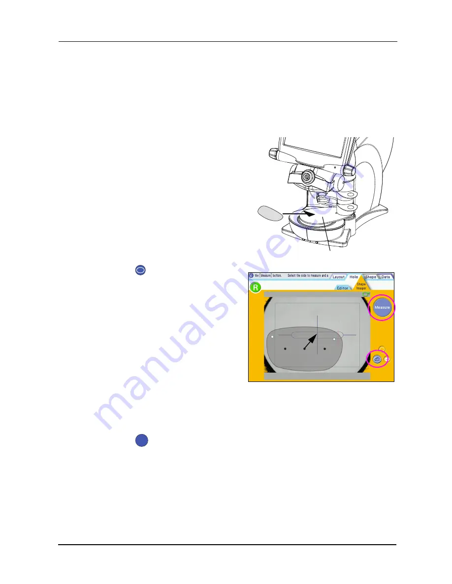
Measuring demo lenses (with marking)

Attach the lens table (for Shape Imager) to the Ice 900. The Shape Imager screen is
automatically displayed.

For confirmation procedures, see “2.7.2 Attaching the lens table (for Shape Imager)” (page 86).

2

Set a demo lens on the lens table with
its front surface facing up.

3

Press the

button.

4

Align the markings on the demo lens
are on the center and horizontal posi-
tion of the alignment scale.

As the right and left markings and the tilt are automatically corrected, the markings are not neces-
sary to be exactly horizontal.

5

Press the R or L button to specify the left eye or right eye lens.

6

Press the

button.

“Wait while measuring.” is displayed on the information bar during measurement. Wait for a
while without touching the instrument.

Lens table

● ● ●

Measure

Summary of Contents for Ice 900

Page 1: ...OPERATOR S MANUAL OPERATOR S MANUAL Intelligent blocker ...

Page 2: ...yo Ku Tokyo 113 0033 Japan Telephone 81 3 5844 2641 Facsimile 81 3 5844 2642 NIDEK INCORPORATED 47651 Westinghouse Drive Fremont California 94539 U S A United States Agent Telephone 1 510 226 5700 Facsimile 1 510 226 5750 NIDEK S A Europarc 13 rue Auguste Perret 94042 Créteil France EU Authorized Representative Telephone 33 1 49 80 97 97 Facsimile 33 1 49 80 32 08 October 2009 44601 P912A Printed ...

Page 3: ...Keep this manual handy for reference If you encounter any problems or have questions about the instrument please contact NIDEK or your authorized distributor In this manual signal words are used to designate the degree or level of safety alerting The defi nitions are as follows CAUTION Indicates a potentially hazardous situation which if not avoided might result in minor or moderate injury or prop...

Page 4: ...r contains poisonous gas or liquid Corrosion or malfunction of the instrument may occur Install the instrument in a location with an adequate operating area in front of the instrument as illustrated on page V Be sure to use a wall outlet which meets the power specification requirements If the line voltage is too high or too low the instrument may not perform properly Mal function or fire may resul...

Page 5: ...our authorized distributor Be sure to make the correct material selection for the lens material being processed If an improper material is selected the lens may break or the processing wheels lifetime may be reduced substantially Do not press the Blocking Start button when no lens is placed on the lens table Doing so could cause contact of the cup holder to pins of the lens table Never press on th...

Page 6: ...onditions Temperature 15 to 65ºC 5 to 149ºF Humidity 20 to 85 non condensing A place with low dust A place not exposed to direct sunlight To transport the instrument use the special packing materials to protect from shock and impact Excessive vibration or impact to the instrument may cause malfunction CAUTION Be sure to perform inspections before and after use It is recommended to have periodic pe...

Page 7: ...onents It is recommended to commission the disposal to a designated industrial waste disposal contractor When disposing of packing materials sort them by material and follow local ordinances and recycling regulations Maintenance work area Approximately 500 mm Approximately 500 mm Approximately 500 mm Operating area Approximately 1000 mm Approximately 500 mm ...

Page 8: ...VI ...

Page 9: ...ker Lab system 31 2 1 4 Operation flow of the Blocker VCA system 32 2 2 Getting Started and Exiting 33 2 3 Data Saving Loading and Control 34 2 3 1 For JOB PTN TMP data 34 2 3 2 Saving JOB PTN and TMP data in the internal memory 34 2 3 3 Loading JOB data saved in the Ice 900 36 2 3 4 Loading PTN data saved in the Ice 900 37 2 3 5 Data control 38 2 4 Operating Procedures 41 2 4 1 Operation in the B...

Page 10: ...r lens holder 100 2 9 Initial Screen Customize function 102 2 10 Daily Checks 104 3 MAINTENANCE 105 3 1 Troubleshooting 105 3 2 Replacing Fuses 106 3 3 Setting Clock 107 3 4 Adjusting the Cup Holder 108 3 5 Cleaning 109 3 6 List of Consumables 110 4 CONNECTION AND SETTINGS 111 4 1 Setting Parameters 111 4 2 Connection 118 4 2 1 Connection samples 118 4 2 2 Setting the Ice 900 124 4 2 3 Setting con...

Page 11: ...be stored and controlled in the internal memory is 30 000 or less Blocker Lex Mini Lab system The maximum number of data to be saved depends on the size of the data The Ice 900 can be directly connected to two lens edgers Blocker Lex Mini Lab system The Ice 900 can be connected to a large scale laboratory processing system With the Shape Editor function the lens shape can be changed to a variety o...

Page 12: ...he left jog dial to select an item or data folder on the screen Cup holder Attaches the lens cup Touch pen Touch pen holder Display panel Left jog dial Cup holder Blocking arm Lens clamp Lens table Reflection protective plate Tray Lens table for Shape Im ager Small diameter lens holder Pilot lamp Right jog dial Blocking system lever Lens clamp lever Fixing pin lens table ...

Page 13: ...emo lens or pattern Be sure not to smudge the table with dirt or fingerprints as it may affect to the instrument performance When the glass is smudged clean the table with a dry soft cloth Small diameter lens holder When blocking a lens if the lens cannot be held with the lens clamp as the demo lens is too small use the small diameter lens holder to hold the demo lens Pilot lamp Instrument startup...

Page 14: ...ower switch Turns on off the Ice 900 Inlet Connect the detachable power cable The inlet is equipped with a fuse holder Fuse holder Two fuses T 1A 250 V are equipped BAR CODE EDGER 1 EDGER 2 LAN TRACER Fan USB flash drive port µ µ BAR CODE connector TRACER connector Power switch Inlet Fuse holder LAN port EDGER 1 connector EDGER 2 connector Display tilt lever ...

Page 15: ...l barcode scanner USB flash drive port Used to connect an optional USB flash drive Fan Lowers the temperature in the instrument The fan automatically runs if the temperature in the instrument rises above the set temperature When the temperature is not above the set temperature the fan stops running This does not indicate a malfunction 1 ETHERNET Standards on wiring and access to the wiring to allo...

Page 16: ...out mode button Safety beveling button Polishing button Frame type button Processing mode button Soft processing mode button Right or Left indication button Information bar Tracer button JOB PTN Screen change tabs Lens material button µ µ Processing image PTN No display The illustration of the lens in the screen display is as viewed from the front side in the right figure Viewed from the front the...

Page 17: ...hanges the screen to the Blocking screen Menu button Displays the Parameter screen Screen customize button Stores the current screen as an initial screen Clock Indicates the current time Pressing this button displays the Clock screen For details see 3 3 Setting Clock page 107 Frame pupillary distance FPD Distance between the right and left frame centers The FPD is calculated by the boxing system R...

Page 18: ...ns type display the width of the segment For easy alignment enter WD in accordance with the width of the segment When Progressive is selected for the lens type display the width of the hidden marking For easy alignment enter WD in accordance with the distance between the hidden markings Lens type button Changes the lens type Single Multi Progressive and Demo lens to be blocked Layout mode button C...

Page 19: ...ions are Polish and None When safety beveling is on the options are Polish None Pol Edge and Pol SFB The Polish option cannot be selected for glass lenses Processing mode button Selects the processing conditions Frame type button Selects the frame type Metal Plastic TwoPoint Nylor Soft processing mode button Toggles soft processing between on and off Lens material button Specifies the lens materia...

Page 20: ...scan the barcode JOB PTN Displays JOB number or PTN number to be saved or loaded Close the keyboard button Changes to the Layout screen or Blocking screen Save button Saves JOB data PTN data Load button Loads JOB data PTN data Close the keyboard button Hyphen input Alphanumeric keyboard entry Save button Load button JOB PTN Delete character Insert character Delete before character ...

Page 21: ...splay this screen JOB PTN Displays JOB number to receive Close the keyboard button Changes to the Layout screen or Blocking screen JOB data receive button Receives JOB data from the host PC Close the key board button Hyphen input Alphanumeric key board entry JOB data receive button JOB PTN Delete character Insert character Delete before character ...

Page 22: ...ton The camera image brightness setting is displayed and pressing sets in the range of OFF 2 dark to 1 bright JOB PTN Displays JOB PTN number specified on the Layout screen Pressing this button changes to the keyboard screen Block Frame center mark Cup mark Camera brightness button JOB PTN Minimum lens diam eter Layout screen dis play button Display magnifica tion button Blocking start button Layo...

Page 23: ... and x2 The x1 display is used to check the shape in actual size Blocking start button Starts blocking Layout data The layout data entered in the Layout screen is displayed Slow blocking button Used when blocking the demo lens Block the lens in slow speed When blocking in slower speed the blocking arm remains stopped at the lowest position Then the message Complete blocking appears and press the O...

Page 24: ...n select Multi for Type from the Blocking screen The items not described in the following are the same as the Blocking screen Single WD Sets the segment mark width unit mm For easy alignment enter WD in accordance with the distance between the markings on the lens Range 15 0 to 45 0 mm in increments of 0 1 mm Segment mark Displays the layout position of the segment When blocking align the lens seg...

Page 25: ... following are the same as the Progressive Blocking screen Single WD Sets the distance between hidden markings unit mm Range 15 0 to 45 0 mm in increments of 0 1 mm EP Height of far vision eyepoint Sets the height of the far vision eyepoint unit mm Range 0 0 to 6 0 mm in increments of 0 1 mm Far vision eyepoint Indicates the position of the far vision eye point entered on the layout screen The mar...

Page 26: ...in the following are the same as the Blocking screen Single WD mark The width of the marking changes according to the WD value entered in the Layout screen Horizontal vertical line By dragging the horizontal or vertical lines with the touch pen the line can be aligned on the shape outline WD mark Horizontal vertical line When blocking in this screen blocking is performed in slow speed When blockin...

Page 27: ...le X Y X Auto or Curve Edit Adjust button Hole depth indication Shape Imager tab R L frame mark Hole position coordinate buttons Hole position indication Undo and redo buttons Hole No display buttons Shape outline Mirror button Hole diameter indication Right or Left indication button Hole add buttons Hole delete button Hole angle button Hole position coordinate indication Hole setting invalid rang...

Page 28: ...according to each hole Horizontal reference position Vertical reference position Hole position indication Displays the current hole position and hole type The currently selected hole is displayed in red Undo and redo buttons Undo the last change or restore the change by undo Hole No display buttons Displays the hole number of the currently selected hole Press or to select a different hole Center T...

Page 29: ...e is displayed Press the numeric button to display the ten key pad and change the hole depth An indication of 0 0 means a bore hole Each hole depth of Jewel hole 1 to Jewel hole 3 depends on the connected ME 1000 and Lex 1000 settings For details of the hole type see Hole type selection and position specification page 84 Hole position coordinate indication Displays the hole coordinate of the curre...

Page 30: ...ole and display is moved and displayed in the center of the screen When the slotted hole or rectangular hole is selected the position of currently selected hole is moved and displayed in the center of the screen This button is used when the currently selected hole is out of the screen Hole position indication The specified hole position is displayed in the red circle or slotted hole rectangle Edit...

Page 31: ...result The screen changes to the Hole Editor screen Enter the hole data Cancel button This button is displayed after completing the measurement Press this button to cancel the measurement result and retry measurement Demo lens manual alignment button This button is pressed to manually align the lens marking or horizontal reference line on the lens to the scale for detection Pattern detection butto...

Page 32: ...rk Locates the lens in the range of rectangle DBL entry field After measurement the DBL entry field is displayed Enter the DBL value Alignment scale Align the marking on the demo lens horizontal reference line or pattern hole to this scale ...

Page 33: ...d and and input buttons are displayed Press the input button to change the shape dimension When the ten key pad is selected the and input buttons are not displayed Undo and redo buttons Undo the last change or restore the change by undo at the maximum of three Step button Select the dimension change step from 0 10 0 25 0 50 with the input button Or when the ten key pad is selected the value can be...

Page 34: ...e used After blocking JOB data is saved in the TMP_DATA folder automatically when the JOB PTN is 0 Folder list This indicates the folder of the stored shape data Folder search button Searches a folder Folder delete button Deletes the selected folder Data load button Loads the selected data to the Layout screen USB backup button Backs up all the data except for TMP data to the optional USB flash dr...

Page 35: ... the left jog dial and the numeric value can be changed by the right jog dial For some values the numeric value cannot be changed with the jog dial To display the ten key pad press the numeric field such as FPD PD BT size and WD Selecting the numeric field displays the ten key pad The numeric value can also be entered by the jog dial Entry clear button Enter button Close the ten key pad Move the t...

Page 36: ...he item can be selected by the left jog dial and the numeric value can be changed by the right jog dial Selection example of the lens material When the pop up menu is displayed the pop up display item cannot be selected by the jog dial Procedure 1 Press the lens material button The pop up menu is displayed Pop up menu Procedure 2 The desired lens material can be selected from the pop up menu ...

Page 37: ...ymbol side of the switch is flipped down the power is not supplied to the blocker The state of the power switch If the symbol side of the switch is flipped down the power is supplied to the blocker Indicates that the instrument must be supplied only with alternating current Indicates fuse 211 9㹼 0 25 3 1 0 0 52 6 2 NIDEK CO LTD 32 5 9 5 4 02 FH 0 1 3 1 㻠㻠㻢㻜㻝㻙㻹㻜㻠㻞㻙㻭 DV PDUNHG 5HSODFH IXVH 51 1 5LVN...

Page 38: ...ts Unpack the contents from the shipping carton and check them The following are included in the standard configuration Main body Power cord Touch pen RS 232C cable Spare fuses 2 units Table for Shape Imager Small diameter lens holder Operator s manual ...

Page 39: ...e 51 Entering layout data 2 5 3 Entering layout data for single vision lenses page 61 2 5 4 Entering layout data for multifocal lenses page 69 2 5 5 Entering layout data for progressive power lenses page 72 Entering JOB Enter JOB as necessary 2 4 1 Operation in the Blocker Lex system page 41 2 3 Data Saving Loading and Control page 34 Blocking 2 8 Blocking page 95 Processing lenses with the lens e...

Page 40: ... Entering layout data 2 5 3 Entering layout data for single vision lenses page 61 2 5 4 Entering layout data for multifocal lenses page 69 2 5 5 Entering layout data for progressive power lenses page 72 Entering JOB Enter JOB as necessary 2 4 2 Operation in the Mini Lab system page 44 2 3 Data Saving Loading and Control page 34 Blocking 2 8 Blocking page 95 Processing lenses with the lens edger Pr...

Page 41: ...he Blocker Lab system page 47 Receiving JOB data 2 4 3 Operation in the Blocker Lab system page 47 From the host PC receive JOB data Blocking 2 8 Blocking page 95 Send JOB data to the host PC at the same time Processing lenses with the lens edger Loading JOB data from the Ice 900 with the lens edger side Lens processing Turning off the Ice 900 ...

Page 42: ...cker VCA system page 49 Receiving JOB data 2 4 4 Operation in the Blocker VCA system page 49 From the VCA server receive JOB data Blocking 2 8 Blocking page 95 Processing lenses with the lens edger Loading JOB data from the VCA server with the lens edger side Lens processing 2 4 4 Operation in the Blocker VCA system page 49 Turning off the Ice 900 ...

Page 43: ...age 118 for the connecting method 4 Turn on the power switch The blocker starts initializing and Ice 900 is displayed on the LCD touch screen After a short interval the layout screen is displayed The Ice 900 is now ready for use 5 When exiting the Ice 900 turn off the power switch Inlet Power switch Power cord CAUTION Be sure to use an outlet equipped with a ground terminal Electric shock or fire ...

Page 44: ...g on the method of number application select among from JOB PTN and TMP and save it Number entry Data storage amount JOB Alphanumeric characters not including hyphen 16 digits maximum When saving in the internal memory a maximum of 500 folders 500 data items per folder and the total of 30 000 or less data items can be saved The maximum number of data to be saved depends on the size of the data PTN...

Page 45: ...imum of 16 digits including the hyphen may be specified The brand name may contain a maximum of 12 digits but must contain at least one alphabet letter If the entered PTN is less than 16 digits 0 s are filled in at the head of the file number Ex If NIDEK 12 is entered it is saved as NIDEK 0000000012 Data storage procedure 1 Press JOB PTN on the Layout screen to display the keyboard screen 2 Enter ...

Page 46: ... JOB folder 2 Use either the touch pen or the right jog dial to select JOB data 3 Press the button to load the JOB data to the Layout screen Set processing conditions and enter layout data in the Layout screen as necessary Loading using a keyboard 1 Press JOB PTN on the Layout screen to display the keyboard screen 2 Enter JOB 3 Press the button to load the JOB data to the Layout screen Set process...

Page 47: ...Control screen 2 Select a file from the Data Control screen 1 Use the touch pen or left jog dial to select a PTN folder 2 Use the touch pen or right jog dial to select PTN data 3 Press the button to load the PTN data to the Layout screen Set processing conditions and enter layout data in the Layout screen as necessary Loading using a keyboard 1 Press JOB PTN on the Layout screen to display the Key...

Page 48: ...r the folder can be selected by the left jog dial and the data can be entered by the right jog dial Press the Data tab on the Layout screen to display this screen As the amount of data increases the time required for saving or loading also increases so delete or move any unnecessary data Data delete button Folder list Rename button Folder delete button Data load button Data list Scroll bar USB bac...

Page 49: ...deleted Data load button Loads the selected data to the Layout screen Data list A display of the data list in the selected folder The desired data can be selected by the touch pen or the right jog dial Scroll bar Pressing the white area with the touch pen moves the screen list one page forward or back USB backup button Backs up all data except TMP data in the internal memory to the optional USB fl...

Page 50: ...er When backup is completed a message is displayed 5 After backup is completed turn off the power of the instrument and remove the USB flash drive CAUTION For the operation endorsement other than the NIDEK specified USB flash drive optional NIDEK is not responsible for it To protect data loss or corruption due to damage to a USB flash drive back up data to other media periodically NIDEK is not res...

Page 51: ...out screen z When tracing with the Lex 1000 built in tracing unit 1 Trace frames or pattern with the Lex 1000 2 After tracing the traced data is automatically transferred from the Lex 1000 to Ice 900 and displayed on the Layout screen z When loading JOB or PTN data saved in the Ice 900 1 Press the Data tab to display the Data Control screen on the Layout screen 2 Select a file from the Data Contro...

Page 52: ... barcode 3 Press the button to store the data 6 Place the right eye lens on the lens table and block it For blocking procedures see 2 8 Blocking page 95 7 Block the left eye lens 8 Store the blocked lens in a tray or such marked with the JOB Identify the stored lens as right or left When blocking only the R Right lens with the initial screen set to L Left press the L Left button to change the scre...

Page 53: ...sends the data with the associated JOB to the Lex 1000 2 The data transferred from the Ice 900 is displayed by the Lex 1000 10 Process the lens with the Lex 1000 Enter the size bevel curve and bevel position as necessary and process the lens When processing both right and left lenses end processing after both lenses are processed If a number of lenses are to be blocked without processing return to...

Page 54: ... unit 1 Trace frames or pattern with the connected LT 900 2 After tracing press the button on the Layout screen After tracing the traced data is automatically transferred from the LT 900 to Ice 900 and displayed on the Layout screen z When loading JOB or PTN data saved in the Ice 900 1 Press the Data tab to display the Data Control screen on the Layout screen 2 Select a file from the Data Control ...

Page 55: ...Enter JOB If a barcode scanner is connected scan a barcode 3 Press the button to store the data 6 Place the right eye lens on the lens table and block it For blocking procedures see 2 8 Blocking page 95 7 Block the left eye lens When blocking only R Right lens with the initial screen is set to L Left press the L Left button to switch the screen to R Right lens display Enter the grooving or drillin...

Page 56: ...ed from the Ice 900 is displayed by the ME 1000 10 Process the lens with the ME 1000 Enter size bevel curve and bevel position as necessary and process the lens When processing both right and left lenses end processing after both lenses are processed Processing conditions that differ between the right and left lenses cannot be set to the same JOB The processing conditions for the later blocking ar...

Page 57: ...Started and Exiting page 33 2 Enter JOB 1 Press JOB PTN on the Layout screen to display the keyboard screen 2 Enter JOB If a barcode scanner is connected scan a barcode 3 Press the button The JOB data is displayed on the Layout screen 3 Place the right eye lens on the lens table and block it For blocking procedures see 2 8 Blocking page 95 Upon the completion of blocking the JOB data is automatica...

Page 58: ...t processing mode A data transfer request is sent to the Ice 900 2 The Ice 900 receives a request from the ME 1000 It sends the data with the associated JOB to the ME 1000 3 The data transferred from the Ice 900 is displayed by the ME 1000 7 Process the lens with the ME 1000 Enter the size bevel curve and bevel position as necessary and process the lens Processing conditions that differ between th...

Page 59: ...and Exiting page 33 2 Enter JOB 1 Press JOB PTN on the Layout screen to display the keyboard screen 2 Enter JOB If a barcode scanner is connected scan a barcode 3 Press the button The JOB data is displayed on the Layout screen 3 Place the right eye lens on the lens table and block it For blocking procedures see 2 8 Blocking page 95 4 Block the left eye lens JOB PTN Òåãåéöå When the barcode scanner...

Page 60: ...he Ice 900 2 The Ice 900 receives a request from the ME 1000 It sends the data with the associated JOB to the ME 1000 3 The data transferred from the Ice 900 is displayed by the ME 1000 7 Process the lens with the ME 1000 Enter the size bevel curve and bevel position as necessary and process the lens Processing conditions that differ between the right and left lenses cannot be set to the same JOB ...

Page 61: ...ng processing conditions As the processing conditions set the lens material frame type processing mode polishing safety beveling lens type and soft processing mode Lens material Select a lens material Pressing the lens material button displays the pop up menu Press the desired lens type button to select from the following The lens material can also be selected by the jog dial Entering layout data ...

Page 62: ...elect a frame type Pressing the frame type button displays the pop up menu Press the desired frame type button to select from the following The frame type can also be selected by the jog dial For details see 1 3 9 Pop up menu page 26 Metal Plastic celluloid frame Two Point Nylor CAUTION Be sure to select the correct lens material Failure to do so could shorten the useful life of the processing whe...

Page 63: ...ents Metal Plastic Auto No bevel guided processing mode According to the lens edger the guided processing mode cannot be set Guide With bevel guided processing mode High base curve auto processing No bevel guided processing mode High base curve guided processing With bevel guided processing mode Two Point Flat edging Fixed as Flat edging Nylor Auto No grooving guided processing mode Guide With gro...

Page 64: ... 1 Press HC Auto or HC Guide 2 Press the button to display the pop up menu of the high curve bev eling setting 3 Press the value next to the Position and Height button and enter the desired value using the displayed ten key pad Press the button to confirm the value 4 Press the button to close the pop up menu HC Auto or HC Guide is specified Setting HC Auto applies the high base curve auto beveling...

Page 65: ...displays the pop up menu Press the desired polishing type button to select from the following Image of polishing The polish option can also be selected by the jog dial For details see 1 3 9 Pop up menu page 26 None Polish None Polish Pol Edge Pol SFB Polishing button Image of polishing Polishing options Image of polishing If the safety beveling is set to None no pop up menu appears and the Polish ...

Page 66: ...on displays the pop up menu Press the desired safety beveling type button to select from the following Image of safety beveling The safety beveling option can also be selected by the jog dial For details see 1 3 9 Pop up menu page 26 None SFB None Safety beveling Small Medium Large Special Safety beveling button Image of safety beveling Safety beveling button Image of safety beveling For the setti...

Page 67: ...t processing mode button to select from the following Soft processing mode is set to on with the button display Soft processing mode is set to off with the button partial display Lens type button When Demo lens is selected the screen changes to the screen for demo lens blocking For details see 2 8 1 Blocking demo lenses use the small diameter lens holder page 100 For soft processing in the Ice 900...

Page 68: ...o display the pop up menu for setting grooving details 5 Enter the curve type grooving position grooving depth and grooving width in the pop up menu for setting grooving details Curve 1 Press the Curve button The pop up menu is displayed When processing mode is set to Guide the pop up menu is not displayed The menu is fixed to Curve and Auto The setting is possible only when the Ice 900 is connect...

Page 69: ... 12 7 mm Auto Computer calculated curve Curve Manually enter the desired curve Pressing the numeric button displays the ten key pad Enter the desired value Front Front base curve curve profiling the front surface of a lens Rear Rear base curve curve profiling the rear surface of a lens Ratio Select the groove position on the edge by the ratio Pressing the numeric button displays the pop up submenu...

Page 70: ...the button to close the groove details setting menu The default displayed on the Depth numeric button can be specified by setting the Groove Depth parameter The default displayed on the Width numeric button can be specified by setting the Groove Width parameter When Curve is set to other than Auto or when the groove position has been changed ensure that desired groove specifications are displayed ...

Page 71: ...ot entered the corresponding numeric button is highlighted in yellow 1 Select Single for the lens type from the Lay out screen 2 Press the FPD or DBL numeric button to display the ten key pad Enter any value and press the button The range of the FPD value is 30 00 to 99 50 mm in increments of 0 01 mm Pressing the CE button clears the entered value The numeric value can also be entered by the jog d...

Page 72: ...tting The range of the FPD value converted from the DBL value can be entered in the range of 30 00 to 99 50 mm in increments of 0 01 mm 3 Press the PD or 1 2PD numeric field to display the ten key pad Enter any value and press the button The range of the PD value is 30 00 to 99 50 mm in increments of 0 01 mm The numeric value can also be entered by the jog dial The numeric value can be entered in ...

Page 73: ...e entered It is possible to enter the distance from the bridge center to each eye separately Pressing the PD button displays the pop up menu Press 1 2PD to change to the 1 2 PD input setting The range of the 1 2PD value is 15 00 to 49 75 mm in increments of 0 01 mm 1 2PD R 1 2PD L ᵃᵍᵁ Optical center height ǽ ᵍᵁ ...

Page 74: ...oint of the lens shape PD or BT Pressing the button displays the pop up menu Press the PD or BT button to change the entry method The numeric value can also be entered by the jog dial For details see 1 3 8 Ten key pad screen page 25 Enter the optical center height from the frame center The minus mark indicates that the optical center is shifted downward The plus mark indicates that the optical cen...

Page 75: ... the jog dial The numeric value can be entered in increments of 0 05 mm For details see 1 3 8 Ten key pad screen page 25 The lens shape is enlarged or reduced laterally while maintaining a similar form At this time the optical center is regarded as the reference posi tion For example to the right Size 5 mm 6 Select Active Passive Layout mode The default displayed on the optical center height numer...

Page 76: ...r frame center Pressing the Active or Passive button changes the layout mode between Active and Passive Active The lens is blocked with the lens cup at the optical center Passive The lens is blocked with the lens cup at the boxing frame center When HC Auto or HC Guide is selected for Mode or Multi for Type the layout automatically enters Passive mode ...

Page 77: ...o Pliable cup Nano cup When the Cup mode parameter is set to Half eye or Pliable the displayed cup mark is constant in size However when the lens shape contacts the circle of the cup mark the cup mark changes from the yellow to red to give caution When the Cup mode parameter is set to Pliable Pliable Mini or Pliable Nano the settings of the Minimum edging H size and Minimum edging V size parameter...

Page 78: ...epending on the space between the markings on the lens In accordance with the space between the markings set the position easily to be aligned Range 15 0 to 45 0 mm in increments of 0 1 mm It is also possible to set the WD just before placing the lens on the lens table and blocking the lens Setting the alignment scale The height of the horizontally long ellipse of alignment scale can be changed by...

Page 79: ...o prescription enter lens layout data FPD near PD and optical center height 1 Select Multi for the lens type from the Layout screen 2 Enter FPD or DBL 3 Enter the prescribed near PD value PD for the segment in the PD or 1 2PD numeric field 4 Select a method to enter the optical cen ter height Press the button to display the pop up menu Press the PD or BT but ton to change the entry method Changing...

Page 80: ...ails see 1 3 8 Ten key pad screen page 25 6 Enter the size enlarged or reduced lateral based size of lens shape For details of this operation see 5 Enter the size enlarged or reduced lateral based size of lens shape page 65 of 2 5 3 Entering layout data for single vision lenses PD Enter the distance from the center point on the top line of the segment straight down to the point on the lens shape B...

Page 81: ...also be entered by the jog dial The numeric value can be entered in increments of 0 5 mm For details see 1 3 8 Ten key pad screen page 25 The WD represents the distance between the vertical lines on the right and left In accordance with the segment size set the position eas ily to be aligned the position Range 15 0 to 45 0 mm in increments of 0 1 mm It is also possible to set the WD just before pl...

Page 82: ...al When blocking based on far vision eyepoint mark Enter lens layout data using the printed far vision eyepoint mark on the lens 1 Enter EP value according to the pre scription EP value range 0 0 to 6 0 in increments of 0 1 mm 2 Align the far vision eye point mark and the center position of the lens far vision Then align the tilt of the holizontal reference lines and perform blocking When blocking...

Page 83: ...D or 1 2PD numeric field 4 Select a method to enter the optical cen ter height Pressing the button displays the pop up menu Press the PD or BT but ton to change the entry method Select either of the following PD Enter the distance between the far vision eyepoint and straight down point of the lens shape BT Enter the distance between the far vision eyepoint and the lowest point of the lens shape ÐÄ...

Page 84: ...d screen page 25 When the EP value is entered the far vision eyepoint mark changes as shown in the fig ure For the WD in accordance with the space between the hidden markings set the posi tion that is easily aligned Pressing the WD numeric button displays the ten key pad Enter any value and press the but ton The range is 15 0 to 45 0 mm in increments of 0 1 mm 7 Enter the size enlarged or reduced ...

Page 85: ...thod to determine the area that is not to be changed and other area that can be changed 1 Display the original shape data on the Layout screen 2 Press the Shape tab The Shape Editor screen is displayed Lens shapes are displayed in actual size on the Shape Editor screen As a guide for changing loaded shape data to the desired shape the eye image can be changed among adult woman child and adult man ...

Page 86: ...ton to change to fixed area specification mode Numeric values disappear and a section of the lens shape is displayed in yellow At the ends of the yellow line handles yellow squares are displayed 2 Drag the handle with the touch pen to change the fixed area The fixed area can be changed at both ends When the fixed area is not displayed the fixed area may be specified by dragging the shape con tour ...

Page 87: ...y not be changed if the area is too small The button or ten key pad is not displayed even if the numeric value displayed in gray is pressed To cancel the fixed area press the Erase button with the Fix area button selected The area displayed in yellow is can celed and the whole shape is dis played in blue The changing method varies according to whether a fixed area is specified or not Therefore sim...

Page 88: ...d value 3 Press the input button to change the value to the desired value When using the jog dial select the numeric field with the left jog dial and change the numeric value with the right jog dial However when the ten key pad is displayed the jog dial cannot be used 4 Check the post edit shape on the screen Shape edit by dragging 1 Click the area to be changed with the touch pen and change it to...

Page 89: ...hen the Hole Editor screen is displayed after the change the coordinates from the center moved by the change are displayed Step Increases or decreases with the ten key pad or button Undo Undoes the last change undo function Up to three changes can be restored Redo Restores the change by undo redo function Undo operation can be canceled Clear Cancels all changes performed in Shape Editor mode Switc...

Page 90: ...diameter and hole depth Change the value with the ten key pad displayed by pressing each numeric field The setting is possible only when the Ice 900 is connected to an edger ME 1000 Lex 1000 Lex Drill system or SE 9090 Express AHM 1000 system having the drilling function The drilling process can be set in all frame types Metal Plastic Two Point and Nylor When the lens material is Glass or the layo...

Page 91: ...just button place the demo lens on the lens shape display and magnified display to align the hole position Horizontal reference position Vertical reference position When the vertical reference position is set to Center When the vertical reference position is set to B Edge Center The frame center is regarded as the reference position B Edge The temporal end or nasal end of the lens shape is regarde...

Page 92: ... axis horizontal direction and Y axis vertical direction tilt In the Y axis vertical direction with 0 it becomes parallel to the clamp shaft Entering a positive value tilts the hole upward and downward in the direction of the clamp axis In the X axis vertical direction with 0 it becomes parallel to the clamp shaft Entering a positive value tilts the hole right and left in the direction of the clam...

Page 93: ...ss the hole No display button to select the desired hole The hole color changes to red and hole coordinate is displayed and becomes editable Press the button to restore the selection Press the button to select the next hole When selecting the hole with the touch pen Press around the next hole center to select The hole color changes to red and hole coordi nate is displayed and becomes editable QNG ...

Page 94: ...Diameter of the hole and counterbore Depth Depth of the hole and counterbore Jewel hole 1 Hole for embedding a jewel Set with the Jewel Hole 1 parameter in the ME 1000 or Lex 1000 Specify the hole center position Diameter Depth Jewel hole 2 Hole for embedding a jewel Set with the Jewel Hole 2 parameter in the ME 1000 or Lex 1000 Specify the hole center position Diameter Depth Jewel hole 3 Hole for...

Page 95: ...ch settings by selecting it displayed in red with the hole number The coordinate specification method of notched holes is selectable between Center and Edge with the Slot coordinate mode parameter Distance between the holes The reference is the center of the hole nearer to the frame center Distance between the hole and notch at the setting of Center Notch height Hole diameter The notch is automati...

Page 96: ...ert the lens table for Shape Imager into the fixing pin 4 After the lens table for Shape Imager is attached the lens clamp lever lowers and becomes fixed when released Now attachment is completed When there is any dust or fingerprints on the lens table for Shape Imager or reflection protective plate it may affect the proper detection of the lens shape or the measurement time becomes longer In such...

Page 97: ... width to the front side When safety beveling is not performed the edge is not reflected clearly and the shape is not detected correctly It may result in unevenness in the processed lens edge If polish beveling is performed the shape may not be detected correctly In this case per form safety beveling without polishing again When there is any dust on the demo lens lens table for Shape Imager or sur...

Page 98: ...with its front surface facing up 3 Press the button 4 Align the markings on the demo lens are on the center and horizontal posi tion of the alignment scale As the right and left markings and the tilt are automatically corrected the markings are not neces sary to be exactly horizontal 5 Press the R or L button to specify the left eye or right eye lens 6 Press the button Wait while measuring is disp...

Page 99: ...aligned later When dragging is performed with the screen pressed the hole moves with the dragging Press the hole delete button to delete the circle displayed in red Cancel Cancel If Measurement completed Failed to align axis is displayed on the information bar axis alignment failed Check that the WD setting of the single vision lens is fit in the distance between markings on the right and left of ...

Page 100: ... any value and press the button For details of button operation see 2 7 1 Setting entry in the Hole Editor screen page 80 4 For paired or notched holes adjust the distance between the holes Selected hole position move button Edit The hole position detected with the Shape Imager function is a guide The hole detailed position must be specified For the hole that is not detected enter hole with the to...

Page 101: ...next hole center to select The hole color changes to red and hole coordi nate is displayed and becomes editable 14 In the same manner set the position and diameter for all holes 15 After hole specification is completed press the Layout tab to return to the Layout screen The value on the Diameter numeric button is also applied to the diameter of the paired holes or the width of notched holes Next h...

Page 102: ...92 OPERATING PROCEDURES Drilling Settings 16 To save the shape data press the JOB PTN After entering the JOB or PTN with the displayed keyboard press the button to save the data Óáöå ...

Page 103: ...are not necessary to be exactly horizontal Completely remove any pattern s burrs that occur in the pattern refer ence holes as axis alignment may not be performed Only the pattern for two point frames is supported As patterns for Metal Plastic Nylor frame the size is not fit so use the tracer If Measurement completed Failed to align axis is displayed on the information bar axis alignment failed Wh...

Page 104: ... If the demo lens with marking or pattern angle correction error occurred measure with this mode 1 Press the button 2 Align the marking on the demo lens horizontal reference line or pattern hole to the alignment scale on the Shape Imager screen 3 Align the marking on the demo lens horizontal reference line or pattern hole are on the center and horizontal position of the alignment scale on the Shap...

Page 105: ...g Use the color lens cup appropriate to the lens being processed as indicated below for preventing mistakes in processing of right and left lenses CAUTION Before starting blocking do not insert hands into the lens clamp After blocking keep the hands away from the instrument as the lens clamp lowers and blocking arm rotates to return to the original position Fingers may get caught resulting in inju...

Page 106: ...jected on the screen position the center of the lens at an approximate cen ter of the lens table 3 Secure the lens with the lens clamp Support the lens clamp lever by hand and slowly lower it If the lens clamp cannot securely hold the lens readjust the lens position Should the lens be insufficiently secured improper blocking may result 4 Align the lens position Trim away Trim away Double coated ad...

Page 107: ...e screen in actual size and determine whether or not the lens outline sufficiently matches the entered layout conditions If the lens shape extends beyond the lens outer edges replace the lens with a larger diameter lens When the lens size is insufficient for processing for frame changing if a part of the lens shape overlaps lens outline change the lens layout data so that the shape is moved inside...

Page 108: ... lens cup is set in the cup holder 1 Press the blocking start button Or rotate the blocking arm slightly in the direction of arrow 1 by hand 2 The blocking arm rotates and the lens table moves upward to start blocking After block ing the lenses the blocking arm returns to the upper position Far vision eyepoint mark If the markings are difficult to see because of the dark color lenses adjust the im...

Page 109: ...on the screen is pressed the blocking arm returns to the upper position It is possible to set the time that the blocking arm descends with the Lens holding time parameter For confirmation procedures see 4 1 Setting Parameters page 111 When one side blocking is finished the lens display L and R automatically switch Blocking start button Slow blocking button 1 2 For the Small diameter lens when chan...

Page 110: ...lace the small diameter lens holder in the orientation as shown in the figure on the right and fit the three holes of the small diameter lens holder into the three fixing pins of the lens clamp Slowly lower the lens clamp lever 3 Set the lens cup with the double coated adhesive pad to the cup holder For details see 2 8 Blocking page 95 For the demo lens when the lens cannot be hold with the three ...

Page 111: ... vertical line with the touch pen to align it with the shape outline of the lens 6 Block the lens 1 Press the blocking start button Before pressing the button confirm that the lens cup is set in the cup holder 2 The blocking arm remains rest at the low est position 3 When the OK button for Complete block ing displayed on the screen is pressed the blocking arm returns to the upper posi tion 7 Press...

Page 112: ...rial CR39 Hi Index Polyca Acrylic Urethane Trivex Glass Lens type Single Multi Progressive Demo lens Frame type Metal Plastic Two Point Nylor Polishing mode Safety bevel WD Single Multi Progressive Hole Editor screen Horizontal reference position Vertical reference position Shape Editor screen Step 0 01 0 25 0 50 Tenkey Eye image adult woman child and adult man non display The setting between Righ...

Page 113: ...perations to save the screen 1 Display the screen to be saved as the initial settings 2 Change each item to the desired setting 3 Press the screen customize button The operation procedures on the Lay out screen are the same on the Hole Editor screen and Shape Editor screen Screen customize button ...

Page 114: ...firm that there are no foreign substances and dirt on the lens table 2 Does the Layout screen appear when the instrument is started 3 After loading the lens shape and setting the lens does the blocking arm move properly by pressing the blocking start button Check after use 1 Is the power turned off 2 Is the Ice 900 dirty or damaged 3 Are all the accessories accounted for and free from damage Opera...

Page 115: ...e them with new ones See 3 2 Replacing Fuses page 106 for fuse replacement The lens cup cannot be inserted to the cup holder smoothly or easily detached Adjust the plunger of the cup holder For the adjustment method of the plunger see 3 4 Adjusting the Cup Holder page 108 Display of Block arm upper movement error Display of Block arm lower movement error Display of Block arm sensor error upper Dis...

Page 116: ...m the inlet 4 Pull out the fuse holder next to the inlet Pull out the fuse holder while pushing the nail in the arrow direction 5 Take out the fuses and put in new ones Fuse rating T 1A 250 V 6 Put the fuse holder back into its original posi tion CAUTION Be sure to turn the power off and disconnect the power cord from the outlet before replacing the fuses Electric shock may occur Only the specifie...

Page 117: ... year month day time and Set buttons are displayed on the Clock screen 3 As necessary select the display format by pressing the Date format Date format yyyy mm dd year month day dd mm yyyy day month year mm dd yyyy month day year 4 Press year month day and time change buttons to display the ten key pad and enter the desired value 5 After all changes press the Set button Pressing the Set button upd...

Page 118: ...ld the lens cup securely To tighten the plunger insert the hexagonal head wrench into the hole at the top of the cup holder and turn the plunger Adjust the cup holder so that the cup holder can securely hold the lens cup and that the lens cup can be detached or inserted smoothly Turn the plunger clockwise to increase the holding power of the lens cup Plunger ...

Page 119: ...tly Be sure not to get dirt or fingerprints on the reflection protective plate Should the plate become dirty clean the glass with dry soft cloth CAUTION Never use an organic solvent such as paint thinner This could damage the surface Lightly wipe the exterior of the LCD touch screen with a soft cloth Do not press the LCD touch screen using an object with a hard tip In addition keep magnetic object...

Page 120: ...een 40370 M095 For right lenses Double coated adhesive pad 40370 M087 For pliable cup 1 set 100 sheets Lens cup for half eye lens White 40370 M061 For general lenses Lens cup for half eye lens Blue 40370 M066 For flat lenses Lens cup for half eye lens Pink 40370 M068 For plus lenses Double coated adhesive pad 40370 M071 Lens cup for half eye lens Mini cup 40370 M098 Double coated adhesive pad Cut ...

Page 121: ...cedure z For the parameters whose settings must be selected from the provided options the pop up menu appears 1 Press the button for the desired parameter setting 2 The entry is confirmed and the pop up closes Select the parameter with the left jog dial and the settings can be changed with the right jog dial z For the parameters whose settings must be specified by values the ten key pad is display...

Page 122: ... and the pilot lamp blinks To restore from standby mode press the LCD touch screen rotate the jog dial or rotate the blocking arm slightly downward 4 Pilot LED brightness Off Dark Light Factory setting Light Adjusts the brightness of the pilot lamp If Off is set the light still turns on temporarily when the power is turned on 5 Polish SFB setting Le Lex Se Me Factory setting Le Lex This parameter ...

Page 123: ...etting 38400 Sets the communication speed Baudrate using EDGER1 2 and TRACER port Regardless of this setting communication speed with the barcode scanner is fixed at 9600bps 3 My ID 1 to 65535 Factory setting 32 This parameter sets the ID No for the Ice 900 When multiple Ice 900 units are connected in a network set any number from 1 to 65535 as an identification number 4 Host ID No 1 to 65535 Fact...

Page 124: ...ue of optical center height The value range is 5 0 to 5 0mm in increments of 0 1 mm 2 Default groove Setting On Off Factory setting On with grooving This parameter sets whether or not to perform grooving after turning on loading the traced data measuring the demo lens shape and selecting the nylor frame 3 Groove depth 0 to 0 8 Factory setting 0 3 This parameter is for setting the default groove de...

Page 125: ...lenses that can be processed by a lens edger Set any value from 15 0 to 30 0 mm in increments of 0 1 mm according to the lens edger 4 Minimum grinding V size 15 0 to 30 0 mm Factory setting 20 0 mm This parameter sets the minimum vertical length of halfeye lenses that can be processed by a lens edger Set any value from 15 0 to 30 0 mm in increments of 0 1 mm according to the lens edger Halfeye The...

Page 126: ... the setting of 3 1 seconds The parameter is set to Stop When blocking is performed the blocking arm keeps stopped at the lowest position When the OK button for Complete blocking displayed on the screen is pressed the blocking arm returns to the original position Parameter items and setting contents hole set tings 1 Slot coordinate mode Center Edge Factory setting Center Selects the reference poin...

Page 127: ...nvalid range Parameter items and setting contents clock setting For details of the setting see 3 3 Setting Clock page 107 1 Date format yyyy mm dd dd mm yyyy mm dd yyyy Factory setting dd mm yyyy Selects the display format of the date from the followings yyyy mm dd year month day dd mm yyyy day month year and mm dd yyyy month day year 2 Year Month Day Hour Minute Second yyyy mm dd hh mm ss Indicat...

Page 128: ...ne or two units of Lex 1000 Connecting to the Ice 900 Blocker Lex CAUTION Confirm that all instruments are turned off before connecting them to the Ice 900 Ice 900 Lex 1000 RS 232C ãáâìå optional Lex 1000 BAR CODE EDGER 1 EDGER 2 LAN TRACER Ice 900 Lex 1000 optional Âáòãïäå óãáîîåò RS 232C ãáâìå RS 232C ãáâìå BAR CODE connector EDGER 2 connector EDGER 1 connector Lex 1000 ...

Page 129: ...Hub Mul tifun ctio n Edg er ME 1000 DǽEǽ SǽIǽG ǽNǽᴨ DǽEǽS ǽIǽGǽ Nǽᴨ ME 1000 Mul tifun ctio n Edg er ME 1000 DǽEǽ SǽIǽG ǽNǽᴨ DǽEǽS ǽIǽGǽ Nǽᴨ RS 232C cable LT 900 ME 1000 Mul tifun ctio n Edg er ME 1000 DǽEǽ SǽIǽG ǽNǽᴨ DǽEǽS ǽIǽGǽ Nǽᴨ ME 1000 Mul tifun ctio n Edg er ME 1000 DǽEǽ SǽIǽG ǽNǽᴨ DǽEǽS ǽIǽGǽ Nǽᴨ LAN cable optional optional optional Ice 900 When connecting two lens edgers Ice 900 When conne...

Page 130: ...0 Mini Lab BAR CODE EDGER 1 EDGER 2 LAN TRACER Ice 900 Hub Lex 1000NT LAN cable optional ME 1000 ME 1000 Barcode scanner LT 900 RS 232C cable RS 232C cable RS 232C cable LAN cable LAN port BAR CODE connector TRACER connector EDGER 2 connector EDGER 1 connector ...

Page 131: ... 1000 D ޓ E ޓ S ޓ I ޓ G ޓ N ޓ 㧗 D ޓ E ޓ S ޓ I ޓ G ޓ N ޓ 㧗 ME 1000 Mul tifun ctio n Edg er ME 1000 D ޓ E ޓ S ޓ I ޓ G ޓ N ޓ 㧗 D ޓ E ޓ S ޓ I ޓ G ޓ N ޓ 㧗 LAN cable Hub LAN cable Lex 1000 ME 1000 Mul tifun ctio n Edg er ME 1000 D ޓ E ޓ S ޓ I ޓ G ޓ N ޓ 㧗 D ޓ E ޓ S ޓ I ޓ G ޓ N ޓ 㧗 ME 1000 Mul tifun ctio n Edg er ME 1000 D ޓ E ޓ S ޓ I ޓ G ޓ N ޓ 㧗 D ޓ E ޓ S ޓ I ޓ G ޓ N ޓ 㧗 Host PC RS 232C cable LT 900 Hub ...

Page 132: ...122 CONNECTION AND SETTINGS Connection Connecting to Ice 900 Blocker Lab BAR CODE EDGER 1 EDGER 2 LAN TRACER Ice 900 Hub LAN cable optional Barcode scanner LAN port BAR CODE connector LAN Ethernet ...

Page 133: ...m Connect to the host PC with RS 232C cable via EDGER1 port Connecting to Ice 900 Blocker VCA Ice 900 Host PC RS 232C cable optional BAR CODE EDGER 1 EDGER 2 LAN TRACER Ice 900 Host PC optional Barcode scanner RS 232C cable BAR CODE connector EDGER 1 connector ...

Page 134: ... the port No of the used software Parameter Blocker Lex Mini Lab Blocker Lab Blocker VCA Edger port LAN port My ID Ice 900 ID No 32 ID No of the Ice 900 32 ID No of the Ice 900 Any number except for the Host ID No Host ID Ice 900 ID No 32 ID No of the Ice 900 32 ID No of the host PC Communication speed 38400 38400 38400 Mac Address 1 Never change the factory setting 2 Never change the factory sett...

Page 135: ...Communication Setting screen for settings Parameter Blocker Lex when using RS 232C port Mini Lab when using RS 232C port Mini Lab Blocker Lab when using LAN port Communication setting system Blocker Lex RS 232C Mini Lab RS 232C Mini Lab Ethernet Server ID No Ice 900 ID No 32 Ice 900 ID No 32 ID No of the host PC Ice 900 32 My ID No ID No of the Lex 1000 Any number except for the Server ID No ID No...

Page 136: ...VER No 1 Ice 900 ID No 32 Ice 900 ID No 32 ID No of the server PC ID No 32 My ID No 1 ID No of the Le 1000 Any number except for the Server No ID No of the Le 1000 Any number except for the Server No ID No of the Le 1000 Any number except for the Server No Baud Rate for EXT 1 Set the Baud Rate to the same value as the Ice 900 Set the Baud Rate to the same value as the Ice 900 Set the Baud Rate to ...

Page 137: ...distributor Blocker Lex cannot be connected Parameter Mini Lab when using the RS232C port Blocker Lab Mini Lab when using the LAN port Communication interface LAN LAN COM port Protocol RS232C TCP Baud rate Set the Baud Rate to the same value as the Ice 900 Mac address Never change the factory setting 1 IP address Set the parameter uniquely for each individual SE 9090 Express 2 Subnet mask Set the ...

Page 138: ...when using the LAN port Blocker Lab 1 Communication port RS 232C Ethernet Ethernet 1 Communication interface LAN LAN LAN 1 Baud rate Set the Baud rate to the same value as the Ice 900 1 Protocol TCP TCP 1 Host ID Ice 900 ID No 32 Ice 900 ID No 32 ID No of the host PC 32 ID No 32 1 My ID ID No of the ME 1000 Any number except for the Server No ID No of the ME 1000 Any number except for the Server N...

Page 139: ... 5 kgf FPD 30 00 to 99 50 mm PD 30 00 to 99 50 mm 1 2PD 15 00 to 49 75 mm Optical center height 15 mm Size adjustment 9 95 mm Entry items FPD DBL can be selectable PD 1 2PD can be selectable Optical center height BT height and PD height can be selected Size Lens material CR39 Trivex Hi Index Polyca Acrylic Glass Urethane Frame type Metal Plastic Nylor Two Point Processing specification Polish Safe...

Page 140: ...ter parameter cannot be entered Display 8 4 inch SVGA Color Liquid Crystal Display with touch panel Interface function In compliance with RS 232C 4 ports EDGER1 For connection with a first lens edger or Host PC EDGER2 For connection with a second lens edger TRACER For connection with a tracing unit BAR CODE For connection with a barcode scanner Ethernet 10 100 BASE T one port Data Control function...

Page 141: ...to 31ºC 41 to 88ºF 30 to 80 The minimum acceptable relative humidity is 30 for the temperature range of 31ºC to 40ºC The maximum acceptable relative humidity is 80 for temperatures up to 31ºC which decreases linearly after that to 50 relative humidity at 40ºC Pressure 700 to 1060 hPa Installation location Indoors no harmful dust smoke or vibration etc Temperature 15 to 65ºC 5 to 149ºF Humidity 20 ...

Page 142: ...uration 5 2 1 Standard accessories 5 2 2 Optional accessories Power cord 1 unit Touch pen 1 unit Communication cable RS 232C 1 unit Spare fuse 2 units Lens table for Shape Imager 1 unit Small diameter lens holder 1 unit Operator s manual 1 volume Barcode scanner USB flash drive ...

Page 143: ... Far vision eyepoint 15 Fix area button 23 Fixing pin lens table 3 Folder delete button 24 Folder list 24 Folder search button 24 FPD 7 61 Frame center mark 8 13 Frame type button 9 Fuse holder 4 G Group indication 19 H Hold depth indication 19 Hole add buttons 19 Hole angle button 17 Hole diameter indication 19 Hole Editor screen 17 Hole No display button 18 Hole position coordinate buttons 18 Ho...

Page 144: ...eflection protective plate 3 Rename button 25 Right jog dial 3 Right or Left indication button 7 12 17 S Safety beveling 56 Safety beveling button 8 Save button 10 Screen change tabs 7 Screen customize button 7 Segment mark 14 Selected hole position move button 20 Shape dimension 23 Shape Editor function 23 Shape Imager tab 18 Shape size 8 Slow blocking button 13 Small diameter lens holder 3 Soft ...

Reviews: