90
OPERATING PROCEDURES
:
Drilling Settings
11
After specifying the hole position, press
the
button.
The status changes from the hole
position addition to the hole position
precise setting.
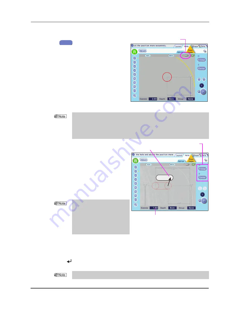
The (red) hole area selected when Edit is pressed is magnified displayed.
12
Specify the precise hole position and hole
diameter.
Drag the hole indication to the hole on the
demo lens image. For paired or notched
holes, align also the distance between the
holes by dragging. Match the hole posi-
tion and diameter displayed in red with
the image.
1) Drag the red circle with the touch pen
to align it with the hole position of the
demo lens.
2) As necessary, press the hole position coordinate button to set the horizontal and vertical
reference position.
3) Adjust the hole diameter.
Pressing the Diameter numeric button to display the ten-key pad. Enter any value and press the
button.
For details of button operation, see “2.7.1 Setting entry in the Hole Editor screen” (page 80).
4) For paired or notched holes, adjust the distance between the holes.
Selected hole position move button
Edit
• The hole position detected with the Shape Imager function is a guide. The hole detailed
position must be specified. For the hole that is not detected, enter hole with the touch pen.
• When the selected hole position move button is pressed, the position of currently selected
hole (red circle) is moved and displayed in the center of the screen. When the slotted hole
is selected, the base point hole is moved and displayed in the center of the screen.
• The hole (broken line) that is
detected with the Shape Imager
function can be decided (solid line)
by changing the hole position and
hole diameter. (Red color when
selected, blue color when not
selected)
Hole position coordinate buttons
Hole diameter indication
Hole of the demo lens
• A value smaller than that set by the Drill bit diameter parameter cannot be set.


