


154
3 PROGRAMMING
3.3 Communication Example of Safety Communication
Settings in the remote stations
Set the IP address set in "Network Configuration Settings" of the master station.
Connect the engineering tool to the Safety CPU of the master station and set parameters of the remote stations.
1.
Set the parameters of the remote station in the "CC-Link IE TSN Configuration" window as shown below and write the
parameters.
[Navigation window]
[Parameter]
[Module Information]
[RJ71GN11-T2]
[Basic Settings]
[Network
Configuration Settings]
Select the NZ2GNSS2-16DTE in the list of stations.
Right-click
[Parameter of Slave
Station]
• For items other than above, write the initial value.
• Select [Close with Reflecting the Setting] to close the "CC-Link IE TSN Configuration" window after writing parameters of
the remote station.
2.
Visually check if the parameter of the remote station is correctly written after writing parameters. For how to check the
parameters, refer to the following.
GX Works3 Operating Manual
3.
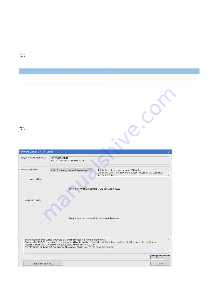
Open the "Command Execution of Slave Station" window in the "CC-Link IE TSN Configuration" window.
[Navigation window]
[Parameter]
[Module Information]
[RJ71GN11-T2]
[Basic Settings]
[Network
Configuration Settings]
Select the NZ2GNSS2-16DTE in the list of stations.
Right-click
[Online]
[Command
Execution of Slave Station]
4.
Select "Start of checking the module position" in "Method selection" and click the [Execute] button.
5.
The SAFETY LED of the NZ2GNSS2-16DTE flashes. Check if the NZ2GNSS2-16DTE on which the SAFETY LED
flashes has been installed on the desired position.
Name
Write value
Wiring selection of input X0
1: Safety double wiring (NC/NC)
Wiring selection of input X1
1: Safety double wiring (NC/NC)
Summary of Contents for MELSEC iQ-R CC-Link IE TSN
Page 1: ...MELSEC iQ R CC Link IE TSN User s Manual Application RJ71GN11 T2 ...
Page 2: ......
Page 323: ...APPX Appendix 10 Added and Enhanced Functions 321 A MEMO ...
Page 325: ...I 323 MEMO ...
Page 329: ......


