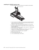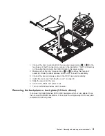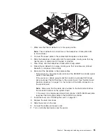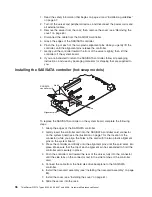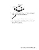
1. Connect the short 4-wire length of the riser-card power cable (
2
to
3
) to the
two halves of the P4 connector, as shown in the illustration. The P4 connector is
on the cable that connects the CD/DVD drive to the power supply.
2. Make sure that the long 2-wire section (
2
to
1
) reaches the riser-card
assembly. Route the cable between fans 4 and 5 to reach the assembly.
3. Connect the riser-card power cable to the PCI-X riser-card assembly.
4. Install the cover (see “Installing the cover” on page 61).
5. Slide the server into the rack.
6. Connect the cables and power cords.
7. Turn on all attached devices and the server.
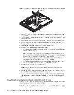
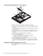
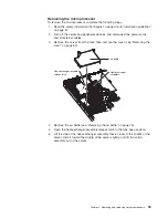
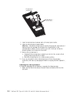
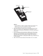
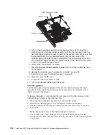
Removing the backplane or back plate (3.5-inch drives)
To remove the Serial Attached SCSI (SAS) backplane, which is also referred to as
the hot-swap SAS/SATA backplane, or to remove the simple-swap SATA back plate,
complete the following steps.
Chapter 4. Removing and replacing server components
91
Summary of Contents for ThinkServer RS110
Page 1: ...ThinkServer RS110 Types 6435 6436 6437 and 6438 Hardware Maintenance Manual ...
Page 2: ......
Page 3: ...ThinkServer RS110 Types 6435 6436 6437 and 6438 Hardware Maintenance Manual ...
Page 8: ...vi ThinkServer RS110 Types 6435 6436 6437 and 6438 Hardware Maintenance Manual ...
Page 18: ...xvi ThinkServer RS110 Types 6435 6436 6437 and 6438 Hardware Maintenance Manual ...
Page 74: ...56 ThinkServer RS110 Types 6435 6436 6437 and 6438 Hardware Maintenance Manual ...
Page 238: ...220 ThinkServer RS110 Types 6435 6436 6437 and 6438 Hardware Maintenance Manual ...
Page 251: ......
Page 252: ...Part Number 46U0856 Printed in USA 1P P N 46U0856 ...


