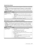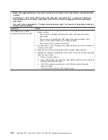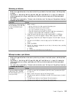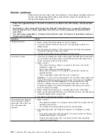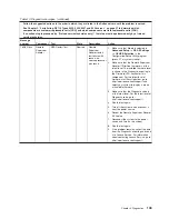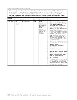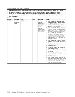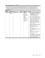
Universal Serial Bus (USB) device problems
v
Follow the suggested actions in the order in which they are listed in the Action column until the problem
is solved.
v
See Chapter 3, “Parts listing, RS110 Types 6435, 6436, 6437 and 6438 server,” on page 27 to determine
which components are customer replaceable units (CRU) and which components are field replaceable
units (FRU).
v
If an action step is preceded by “(Trained service technician only),” that step must be performed only by a
trained service technician.
Symptom
Action
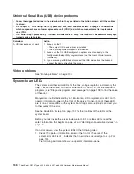
A USB device does not work.
1. Make sure that:
v
The correct USB device driver is installed.
v
The operating system supports USB devices.
2. Make sure that the USB configuration options are set correctly in the
Configuration/Setup Utility program menu (see the
User’s Guide
for more
information).
3. If you are using a USB hub, disconnect the USB device from the hub and
connect the device directly to the server.
Video problems
See “Monitor problems” on page 130.
System-board LEDs
The system board has error LEDs for the fans, voltage regulator, and memory that
help to locate the source of an error. When an error LED is lit, run the diagnostic
programs (see “Diagnostic programs and messages” on page 138) to find the cause
of the error.
Many errors are first indicated by a lit information LED or system-error LED on the
operator information panel on the front of the server. If one or both of these LEDs
are lit, one or more LEDs on the system board might also be lit and can direct you
to the source of the error.
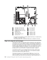
See the illustration in step 7 on page 137 for the locations of the LEDs on the
system board.
Before you look inside the server to view error LEDs or status LEDs, read the
safety information that begins on page vii and “Handling static-sensitive devices” on
page 59.
If an error occurs, view the system LEDs in the following order:
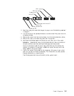
1. Check the operator information panel on the front of the server. If the
system-error LED is lit, it indicates that an error has occurred; go to step 2 on
page 137.
The following illustration shows the operator information panel.
136
ThinkServer RS110 Types 6435, 6436, 6437 and 6438: Hardware Maintenance Manual
Summary of Contents for ThinkServer RS110
Page 1: ...ThinkServer RS110 Types 6435 6436 6437 and 6438 Hardware Maintenance Manual ...
Page 2: ......
Page 3: ...ThinkServer RS110 Types 6435 6436 6437 and 6438 Hardware Maintenance Manual ...
Page 8: ...vi ThinkServer RS110 Types 6435 6436 6437 and 6438 Hardware Maintenance Manual ...
Page 18: ...xvi ThinkServer RS110 Types 6435 6436 6437 and 6438 Hardware Maintenance Manual ...
Page 74: ...56 ThinkServer RS110 Types 6435 6436 6437 and 6438 Hardware Maintenance Manual ...
Page 238: ...220 ThinkServer RS110 Types 6435 6436 6437 and 6438 Hardware Maintenance Manual ...
Page 251: ......
Page 252: ...Part Number 46U0856 Printed in USA 1P P N 46U0856 ...

