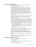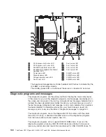
Power-on LED
Power-control button
Reset button
Hard disk drive activity LED
Locator LED
System error LED
USB 1 connector
USB 2 connector
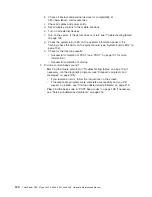
2. Read the safety information that begins on page vii and “Installation guidelines”
on page 57.
3. Turn off the server and peripheral devices, and disconnect the power cord and
all external cables.
4. Remove the server from the rack and place on a flat, static-protective surface.
5. Remove the cover (see “Removing the cover” on page 60).
6. Reconnect all external cables and the power cord; then, turn on the server.
Attention:
Operating the server for extended periods of time (more than 30
minutes) with the cover removed might damage server components.
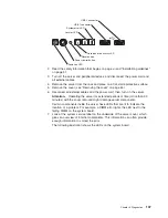
Certain components inside the server have LEDs that are lit to indicate the
location of a problem. For example, a DIMM error lights the LED next to the
failing DIMM on the system board.
7. Look at the system service label on the underside of the server cover, which
gives an overview of internal components. This information can often provide
enough information to correct the error.
The following illustration shows the LEDs on the system board.
Chapter 5. Diagnostics
137
Summary of Contents for ThinkServer RS110
Page 1: ...ThinkServer RS110 Types 6435 6436 6437 and 6438 Hardware Maintenance Manual ...
Page 2: ......
Page 3: ...ThinkServer RS110 Types 6435 6436 6437 and 6438 Hardware Maintenance Manual ...
Page 8: ...vi ThinkServer RS110 Types 6435 6436 6437 and 6438 Hardware Maintenance Manual ...
Page 18: ...xvi ThinkServer RS110 Types 6435 6436 6437 and 6438 Hardware Maintenance Manual ...
Page 74: ...56 ThinkServer RS110 Types 6435 6436 6437 and 6438 Hardware Maintenance Manual ...
Page 238: ...220 ThinkServer RS110 Types 6435 6436 6437 and 6438 Hardware Maintenance Manual ...
Page 251: ......
Page 252: ...Part Number 46U0856 Printed in USA 1P P N 46U0856 ...

