


Attention:
To ensure proper cooling and airflow, do not operate the server
for more than 30 minutes with the cover removed.
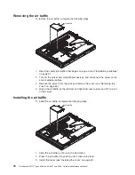
4. Rotate (lift) the air deflector out of the way.
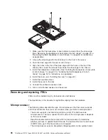
5. If the server is a 3.5-inch drive model, remove the hard disk drive back plate or
backplane (see “Removing the backplane or back plate (3.5-inch drives)” on
page 91).
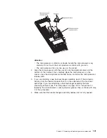
Note:
Note the routing of all power-supply cables; you will route the
power-supply cables the same way when you install the power supply.
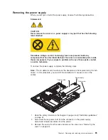
6. Disconnect the power-supply cables from the connector on the system board
and from all devices; then, disengage the cables from any retention-clips that
secure them to the chassis.
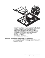
7. Remove the screw that holds the power supply to the rear of the chassis (see
the illustration on page 85).
8. Loosen the captive thumbscrew that secures the rear of the power supply to
the chassis bottom.
9. Lift the power supply out of the bay.
10. If you are instructed to return the power supply, follow all packaging
instructions, and use any packaging materials for shipping that are supplied to
you.
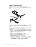
Installing the power supply
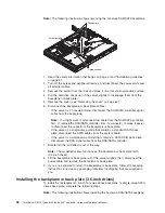
Note:
The air deflector also functions as the backplane or back plate latch (3.5-inch
drives), and covers some of the cables. In this procedure, you must close the air
deflector after you route some of the cables.
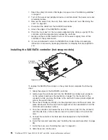
To install the replacement power supply, complete the following steps:
1. Read the safety information in “Working inside the server with the power on”
on page 58.
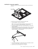
2. Place the new power supply into the bay.
3. Tighten the captive thumbscrew that secures the rear of the power supply to
the chassis bottom.
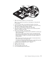
4. Replace the screw that holds the power supply to the rear of the chassis (see
the illustration on page 85).
5. Make sure that the air deflector is in the open position.
6. Connect the internal power-supply cable from the power supply to the power
connector (CN20) on the system board (see “System-board internal
connectors” on page 7).
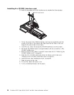
7. Route the other internal power-supply cable, securing it under the
retention-clips on the chassis; then, reconnect the cable to the CD/DVD
interface card.
86
ThinkServer RS110 Types 6435, 6436, 6437 and 6438: Hardware Maintenance Manual
Summary of Contents for ThinkServer RS110
Page 1: ...ThinkServer RS110 Types 6435 6436 6437 and 6438 Hardware Maintenance Manual ...
Page 2: ......
Page 3: ...ThinkServer RS110 Types 6435 6436 6437 and 6438 Hardware Maintenance Manual ...
Page 8: ...vi ThinkServer RS110 Types 6435 6436 6437 and 6438 Hardware Maintenance Manual ...
Page 18: ...xvi ThinkServer RS110 Types 6435 6436 6437 and 6438 Hardware Maintenance Manual ...
Page 74: ...56 ThinkServer RS110 Types 6435 6436 6437 and 6438 Hardware Maintenance Manual ...
Page 238: ...220 ThinkServer RS110 Types 6435 6436 6437 and 6438 Hardware Maintenance Manual ...
Page 251: ......
Page 252: ...Part Number 46U0856 Printed in USA 1P P N 46U0856 ...


