Installing a memory module (DIMM)
The following notes describe information that you must consider when you install
DIMMs:
v
The server comes with one 512 MB or 1 GB DIMM installed in DIMM connector
1 and an identical DIMM (the same size, speed, type, and technology) installed
in DIMM connector 3.
v
If you install a pair of DIMMs in DIMM connectors 2 and 4, the size, speed, type,
and technology of the DIMMs that you install in DIMM connectors 2 and 4 must
match each other. However, they do not have to be the same size, speed, type,
and technology as the DIMMs that are installed in DIMM connectors 1 and 3.
v
You can use compatible DIMMs from various manufacturers in the same pair.
v
If you install a pair of 2 GB DIMMs and a pair of other-size DIMMs, the 2 GB
DIMMs must be installed as the first pair (in DIMM connectors 1 and 3).
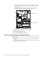
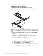
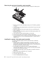
To install the replacement DIMM, complete the following steps.
Attention:
To avoid breaking the retaining clips or damaging the DIMM
connectors, open and close the clips gently.
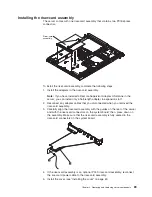
1. Open the retaining clip on each end of the DIMM connector.
2. Touch the static-protective package that contains the DIMM to any unpainted
metal surface on the server. Then, remove the DIMM from the package.
3. Turn the DIMM so that the DIMM keys align correctly with the connector.
DIMM
Retaining
clip
4. Insert the DIMM into the connector by aligning the edges of the DIMM with the
slots at the ends of the DIMM connector. Firmly press the DIMM straight down
into the connector by applying pressure on both ends of the DIMM
simultaneously. The retaining clips snap into the locked position when the DIMM
is seated in the connector. If there is a gap between the DIMM and the retaining
clips, the DIMM has not been correctly inserted; open the retaining clips,
remove the DIMM, and then reinsert it.
5. Install the cover (see “Installing the cover” on page 61).
6. Slide the server into the rack.
7. If you disconnected any cables or power cords to replace the DIMM, connect
the cables and power cords.
8. Turn on all attached devices and the server.
Chapter 4. Removing and replacing server components
75
Summary of Contents for ThinkServer RS110
Page 1: ...ThinkServer RS110 Types 6435 6436 6437 and 6438 Hardware Maintenance Manual ...
Page 2: ......
Page 3: ...ThinkServer RS110 Types 6435 6436 6437 and 6438 Hardware Maintenance Manual ...
Page 8: ...vi ThinkServer RS110 Types 6435 6436 6437 and 6438 Hardware Maintenance Manual ...
Page 18: ...xvi ThinkServer RS110 Types 6435 6436 6437 and 6438 Hardware Maintenance Manual ...
Page 74: ...56 ThinkServer RS110 Types 6435 6436 6437 and 6438 Hardware Maintenance Manual ...
Page 238: ...220 ThinkServer RS110 Types 6435 6436 6437 and 6438 Hardware Maintenance Manual ...
Page 251: ......
Page 252: ...Part Number 46U0856 Printed in USA 1P P N 46U0856 ...

