crystal User Manual
Version: 6.6.0/2
176/459
10. Audio Mix Engine
10.2.5
Setting Up PGM / AUX Buses
"System -> Definition -> Parameter = Aux"
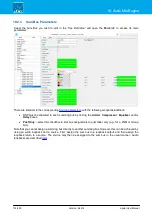
This branch of the 'Tree Definition' defines the 20 summing buses which can be assigned from the control
surface. Note that the bus locations are called
Aux 1
to
Aux 20
, although they may be used for any type of bus:
PGM, REC, AUX, etc.
Once a bus is assigned to an "Aux n" location, it will become available to the operator via the
BUS
assign buttons
on the Central Module (unless the
Hide
option is active). Up to five pages can be configured, where Aux 1 to 4
will appear on page one; Aux 5 to 8 on page two; and so on.
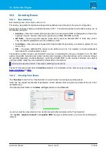
Select "
System
->
Definition
" in 'Tree Definition' and the
Audio
tab to access the "
Parameter
=
Aux
" options:
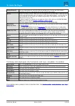
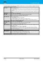
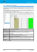
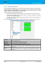
Parameter
Aux – reference name for the element.
Screen Button Text
Defines the text displayed on VisTool "bus assign" buttons. Select
Aux Text
if you wish to inherit the
aux bus Display name.
Aux Mode Sequence
Defines the order in which bus assignments are made; you can select between:
·
Pre - post -off
·
Post - pre - off
"Off", "Pre", "Post"
Colors
Defines the MF Key colors used for aux assignments.
The default colors are Aux Off = green; Aux Pre = red; Aux Post = Yellow.
Aux 1 to 20
Assigns the summing bus defined as “Aux n”.
Hide
Tick this box if you do not want the bus to be displayed on the Fader Module OLEDs when in ‘Bus
Assign’ mode.
Use this option to prevent operators from adjusting assignments onto a bus (e.g. PGM).
Fader Enable
Assigns the control trigger which will switch the bus send levels onto the faders (globally across the
console).

