2NL/2P8
1-2-23
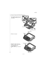
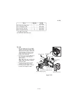
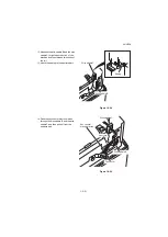
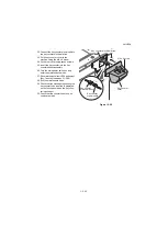
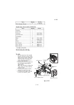
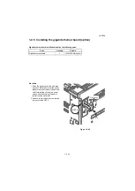
22. Connect the key counter signal cable to
the key counter electrical wires.
23. Fit the key counter cover to the
machine using the M4 x 6 screw.
24. Fit the rear cover using seven screws.
25. Insert the key counter into the key
counter socket assembly.
26. Turn the main power switch on and
enter the maintenance mode.
27. Run maintenance item U204 and select
[Key-Counter] (see page P.1-3-80).
28. Exit the maintenance mode.
29. Check that the message requesting the
key counter to be inserted is displayed
on the touch panel when the key coun-
ter is pulled out.
30. Check that the counter counts up as
copies are made.
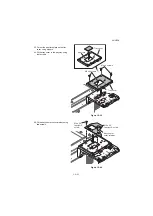
Figure 1-2-28
Key counter
cover
Key counter
elecrtical wires
Key counter electrical wires
Key counter
signal cable
M4 x 6 screw
Summary of Contents for TASKalfa 3010i
Page 10: ...This page is intentionally left blank ...
Page 100: ...2NL 2P8 1 2 76 This page is intentionally left blank ...
Page 286: ...2NL 2P8 1 3 186 This page is intentionally left blank ...
Page 443: ...2NL 2P8 1 5 59 This page is intentionally left blank ...
Page 471: ...2NL 2P8 2 2 8 This page is intentionally left blank ...
Page 532: ...Installation Guide DP 770 B Document processor DP 772 Document processor Installation Guide ...
Page 568: ...DP 773 Document processor Installation Guide ...
Page 594: ...PF 791 500 x 2 Paper feeder Installation Guide ...
Page 602: ...PF 810 3000 sheet deck Installation Guide ...
Page 615: ...DF 791 3000 sheet finisher Installation Guide ...
Page 630: ...DF 770 D 1000 sheet finisher Installation Guide ...
Page 648: ...AK 740 Bridge unit Installation Guide ...
Page 650: ...MT 730 B Mailbox Installation Guide ...
Page 665: ...PH 7A C D Punch unit Installation Guide ...
Page 686: ...DT 730 B Document tray Installation Guide ...
Page 731: ...5 2013 5 302LC56750 01 H F G D D 6 4 3 7 E C D D M4 8 M4 8 M4 8 M4 8 ...
Page 732: ...FAX System W B Installation Guide ...


