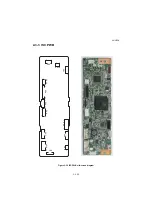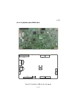
2NL/2P8
2-3-23
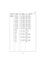
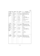
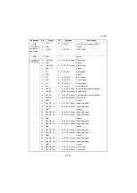
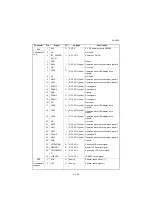
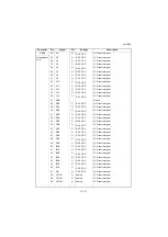
Connector
Pin
Signal
I/O
Voltage
Description
YC3
1
SC_CLK
I
0/3.3 V DC (pulse) Scanner clock signal
Connected to
main PWB
2
SC_SO
O
0/3.3 V DC (pulse) Serial communication data signal
3
SC_SI
I
0/3.3 V DC (pulse) Serial communication data signal
4
SC_BSY
I
0/3.3 V DC
Scanner busy signal
5
SC_HLDN
I
0/3.3 V DC
Scanner hold signal
6
SC_DIR
I
0/3.3 V DC
Scanner communication direction signal
7
SC_IRN
I
0/3.3 V DC
Scanner interrupt signal
8
GND(SPARE)
-
-
Ground
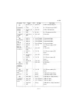
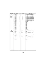
YC4
1
GND
-
-
Ground
Connected to
main PWB
2
HTPDN
O
0/3.3 V DC
Control signal
3
LOCKN
O
0/3.3 V DC
Lock signal
4
GND
-
-
Ground
5
TX0N
O
0/3.3 V DC (pulse) Transmission data signal
6
TX0P
O
0/3.3 V DC (pulse) Transmission data signal
7
GND
-
-
Ground
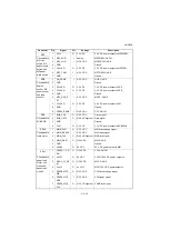
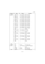
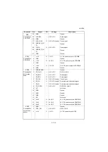
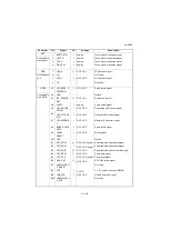
YC5
1
SMOT AP
O
0/24 V DC (pulse)
ISUM drive control signal
Connected to
scanner
motor
2
SMOT BP
O
0/24 V DC (pulse)
ISUM drive control signal
3
SMOT AN
O
0/24 V DC (pulse)
ISUM drive control signal
4
SMOT BN
O
0/24 V DC (pulse)
ISUM drive control signal
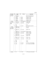
YC6
1
+5V
O
5 V DC
5 V DC power output to LEDPWB
Connected to
LED PWB
2
FAIL
I
0/3.3 V DC
Error signal
3
SDA
I/O
0/3.3 V DC
Data signal
4
SCL
O
0/3.3 V DC (pulse) Clock signal
5
VSET
O
Analog
Analog voltage
6
SGND
-
-
Ground
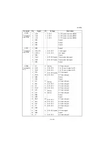
7
PGND
-
-
Ground
8
PWM
O
0/3.3 V DC
PWM signal
9
POW
O
0/3.3 V DC
LED: On/Off
10
+24V1
O
24 V DC
24 V DC power output to LEDPWB
11
+24V1
O
24 V DC
24 V DC power output to LEDPWB
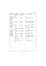
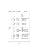
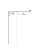
YC7
1
+24V1
I
24 V DC
24 V DC power input from EPWB
Connected to
power sourse
PWB
2
GND
-
-
Ground
3
GND
-
-
Not used
4
GND
-
-
Ground
5
+24V2
I
24 V DC
24 V DC power input from EPWB
6
+24V2
-
-
Not used
Summary of Contents for TASKalfa 3010i
Page 10: ...This page is intentionally left blank ...
Page 100: ...2NL 2P8 1 2 76 This page is intentionally left blank ...
Page 286: ...2NL 2P8 1 3 186 This page is intentionally left blank ...
Page 443: ...2NL 2P8 1 5 59 This page is intentionally left blank ...
Page 471: ...2NL 2P8 2 2 8 This page is intentionally left blank ...
Page 532: ...Installation Guide DP 770 B Document processor DP 772 Document processor Installation Guide ...
Page 568: ...DP 773 Document processor Installation Guide ...
Page 594: ...PF 791 500 x 2 Paper feeder Installation Guide ...
Page 602: ...PF 810 3000 sheet deck Installation Guide ...
Page 615: ...DF 791 3000 sheet finisher Installation Guide ...
Page 630: ...DF 770 D 1000 sheet finisher Installation Guide ...
Page 648: ...AK 740 Bridge unit Installation Guide ...
Page 650: ...MT 730 B Mailbox Installation Guide ...
Page 665: ...PH 7A C D Punch unit Installation Guide ...
Page 686: ...DT 730 B Document tray Installation Guide ...
Page 731: ...5 2013 5 302LC56750 01 H F G D D 6 4 3 7 E C D D M4 8 M4 8 M4 8 M4 8 ...
Page 732: ...FAX System W B Installation Guide ...

