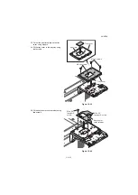
2NL/2P8
1-2-18
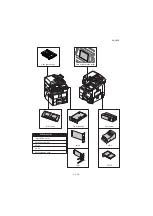
* : Not used in this model.
▲
: One piece is used in this model.
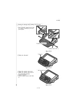
Procedure
1. Press the power key on the operation
panel to off. Make sure that the power
indicator and the memory indicator are
off before turning off the main power
switch. And then unplug the power
cable from the wall outlet.
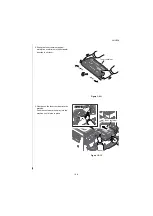
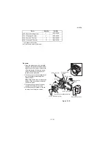
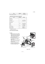
2. Fit the key counter socket assembly to
the key counter retainer using two
screws and nut.
Note:
Take out the wire from the central
portion of the key counter retainer, as
shown in a figure.
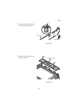
3. Fit the key counter mount to the key
counter cover using two screws.
4. Fit the key counter retainer to the key
counter mount using two screws.
Figure 1-2-19
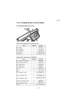
M3 x 8 bronze binding screw
1*
B1B03080
M4 x 30 tap-tight S screw
1*
B1B54300
M4 x 6 chrome TP screw
5
B4A04060
M4 x 10 chrome TP screw
2
B4A04100
Parts
Quantity
Part.No.
M3 x 6 flat-head screw
Key counter
mount
Key counter cover
M4 x 6 screw
Key counter socket assembly
M3 nut
Key counter
retainer
M4 x 6 screw
M4 x 6 screw
M4 x 6 screw
Summary of Contents for TASKalfa 3010i
Page 10: ...This page is intentionally left blank ...
Page 100: ...2NL 2P8 1 2 76 This page is intentionally left blank ...
Page 286: ...2NL 2P8 1 3 186 This page is intentionally left blank ...
Page 443: ...2NL 2P8 1 5 59 This page is intentionally left blank ...
Page 471: ...2NL 2P8 2 2 8 This page is intentionally left blank ...
Page 532: ...Installation Guide DP 770 B Document processor DP 772 Document processor Installation Guide ...
Page 568: ...DP 773 Document processor Installation Guide ...
Page 594: ...PF 791 500 x 2 Paper feeder Installation Guide ...
Page 602: ...PF 810 3000 sheet deck Installation Guide ...
Page 615: ...DF 791 3000 sheet finisher Installation Guide ...
Page 630: ...DF 770 D 1000 sheet finisher Installation Guide ...
Page 648: ...AK 740 Bridge unit Installation Guide ...
Page 650: ...MT 730 B Mailbox Installation Guide ...
Page 665: ...PH 7A C D Punch unit Installation Guide ...
Page 686: ...DT 730 B Document tray Installation Guide ...
Page 731: ...5 2013 5 302LC56750 01 H F G D D 6 4 3 7 E C D D M4 8 M4 8 M4 8 M4 8 ...
Page 732: ...FAX System W B Installation Guide ...

