2NL/2P8
1-2-58
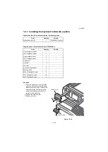
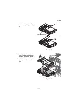
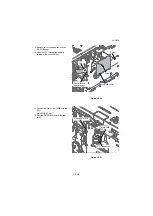
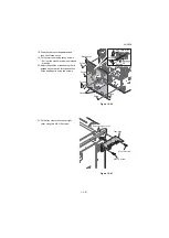
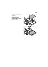
9. Remove two screws and remove the
DP PWB cover.
10. Pass the FFC through the aperture
section of the controller box.
Figure 1-2-80
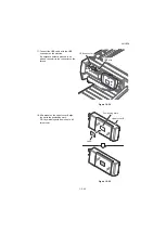
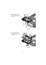
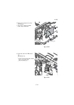
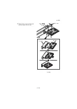
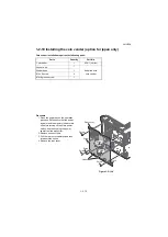
11. Connect the main-circuit PWB with the
FFC.
Main PWB (YC34)
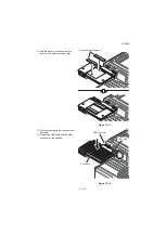
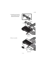
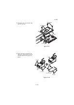
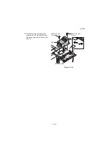
12. Refit the DP PWB cover and the rear
cover.
Figure 1-2-81
Controller box
aperture part
FFC
Screw
Screw
DP PWB cover
FFC connector
Copy guard PWB
Main PWB
YC34
Summary of Contents for TASKalfa 3010i
Page 10: ...This page is intentionally left blank ...
Page 100: ...2NL 2P8 1 2 76 This page is intentionally left blank ...
Page 286: ...2NL 2P8 1 3 186 This page is intentionally left blank ...
Page 443: ...2NL 2P8 1 5 59 This page is intentionally left blank ...
Page 471: ...2NL 2P8 2 2 8 This page is intentionally left blank ...
Page 532: ...Installation Guide DP 770 B Document processor DP 772 Document processor Installation Guide ...
Page 568: ...DP 773 Document processor Installation Guide ...
Page 594: ...PF 791 500 x 2 Paper feeder Installation Guide ...
Page 602: ...PF 810 3000 sheet deck Installation Guide ...
Page 615: ...DF 791 3000 sheet finisher Installation Guide ...
Page 630: ...DF 770 D 1000 sheet finisher Installation Guide ...
Page 648: ...AK 740 Bridge unit Installation Guide ...
Page 650: ...MT 730 B Mailbox Installation Guide ...
Page 665: ...PH 7A C D Punch unit Installation Guide ...
Page 686: ...DT 730 B Document tray Installation Guide ...
Page 731: ...5 2013 5 302LC56750 01 H F G D D 6 4 3 7 E C D D M4 8 M4 8 M4 8 M4 8 ...
Page 732: ...FAX System W B Installation Guide ...


