2NL/2P8
2-3-18
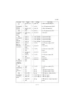
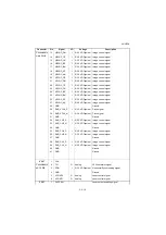
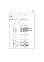
Connected to
main PWB
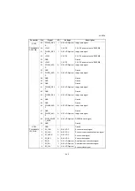
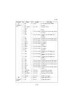
13
HSYNC_DN
I
0/3.3 V DC(pulse) Image control signal
14
HSYNC_CP
I
0/3.3 V DC(pulse) Image control signal
15
HSYNC_CN
I
0/3.3 V DC(pulse) Image control signal
16
HSYNC_BP
I
0/3.3 V DC(pulse) Image control signal
17
HSYNC_BN
I
0/3.3 V DC(pulse) Image control signal
18
HSYNC_AP
I
0/3.3 V DC(pulse) Image control signal
19
HSYNC_AN
I
0/3.3 V DC(pulse) Image control signal
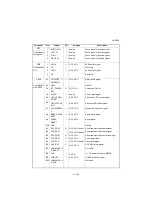
20
VSYNC_DP
I
0/3.3 V DC(pulse) Image
control
signal
21
VSYNC_DN
I
0/3.3 V DC(pulse) Image
control
signal
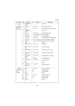
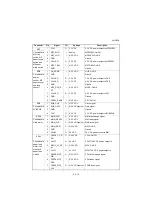
22
VSYNC_CP
I
0/3.3 V DC(pulse) Image
control
signal
23
VSYNC_CN
I
0/3.3 V DC(pulse) Image
control
signal
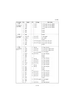
24
VSYNC_BP
I
0/3.3 V DC(pulse) Image
control
signal
25
VSYNC_BN
I
0/3.3 V DC(pulse) Image
control
signal
26
VSYNC_AP
I
0/3.3 V DC(pulse) Image
control
signal
27
VSYNC_AN
I
0/3.3 V DC(pulse) Image
control
signal
28
GND
-
-
Ground
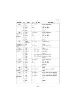
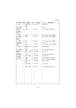
29
SAR_VCLK_P
I
0/3.3 V DC(pulse) Clock signal
30
SAR_VCLK_N
I
0/3.3 V DC(pulse) Clock signal
31
GND
-
-
Ground
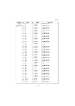
32
SAR_CH3_P
I
0/3.3 V DC(pulse) Image control signal
33
SAR_CH3_N
I
0/3.3 V DC(pulse) Image control signal
34
GND
-
-
Ground
35
SAR_CH2_P
I
0/3.3 V DC(pulse) Image control signal
36
SAR_CH2_N
I
0/3.3 V DC(pulse) Image control signal
37
GND
-
-
Ground
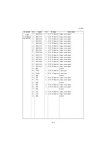
38
SAR_CH1_P
I
0/3.3 V DC(pulse) Image control signal
39
SAR_CH1_N
I
0/3.3 V DC(pulse) Image control signal
40
GND
-
-
Ground
41
GND
-
-
Ground
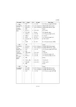
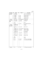
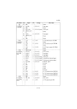
YC27
1
5VIL
Connected to
APC PWB
2
TH
O
Analog
LSU thermistor signal
3
PDN
I
0/3.3 V DC(pulse) Horizontal Synchronizing signal
4
GND
-
-
Ground
5
VCONT2
O
Analog
Laser control signal
6
VCONT1
O
Analog
Laser control signal
YC27
7
OUTPEN
Laser output enabling signal
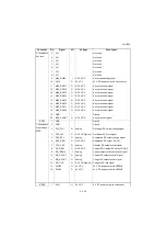
Connector
Pin
Signal
I/O
Voltage
Description
Summary of Contents for TASKalfa 3010i
Page 10: ...This page is intentionally left blank ...
Page 100: ...2NL 2P8 1 2 76 This page is intentionally left blank ...
Page 286: ...2NL 2P8 1 3 186 This page is intentionally left blank ...
Page 443: ...2NL 2P8 1 5 59 This page is intentionally left blank ...
Page 471: ...2NL 2P8 2 2 8 This page is intentionally left blank ...
Page 532: ...Installation Guide DP 770 B Document processor DP 772 Document processor Installation Guide ...
Page 568: ...DP 773 Document processor Installation Guide ...
Page 594: ...PF 791 500 x 2 Paper feeder Installation Guide ...
Page 602: ...PF 810 3000 sheet deck Installation Guide ...
Page 615: ...DF 791 3000 sheet finisher Installation Guide ...
Page 630: ...DF 770 D 1000 sheet finisher Installation Guide ...
Page 648: ...AK 740 Bridge unit Installation Guide ...
Page 650: ...MT 730 B Mailbox Installation Guide ...
Page 665: ...PH 7A C D Punch unit Installation Guide ...
Page 686: ...DT 730 B Document tray Installation Guide ...
Page 731: ...5 2013 5 302LC56750 01 H F G D D 6 4 3 7 E C D D M4 8 M4 8 M4 8 M4 8 ...
Page 732: ...FAX System W B Installation Guide ...


