2NL/2P8
2-2-1
2-2 Electrical Parts Layout
2-2-1 Electrical parts layout
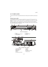
(1) PWBs
Figure 2-2-1 PWBs
1. Main PWB (MPWB) .............................. Controls the software such as the print data processing and
provides the interface with computers.
2. Engine PWB (EPWB)............................ Controls printer hardware such as high voltage/bias output con-
trol, paper conveying system control, and fuser temperature con-
trol, etc.
3. High voltage PWB (HVPWB) ................ Generates main charging, developing bias, transfer bias.
4. Power source PWB (PSPWB) .............. After full-wave rectification of AC power source input, switching
for converting to 24 V DC for output. Controls the fuser heater.
5. Operation panel PWB 1 (OPPWB 1) .... Consists of the LCD, LED indicators and key switches.
6. Operation panel PWB 2 (OPPWB 2) .... Consists of the LED indicators and key switches.
1
7,18
2
3
4
5
6
9
10
8
16
17
12
13 14
15
11
19
Machine inner
Machine front
Machine rear
Summary of Contents for TASKalfa 3010i
Page 10: ...This page is intentionally left blank ...
Page 100: ...2NL 2P8 1 2 76 This page is intentionally left blank ...
Page 286: ...2NL 2P8 1 3 186 This page is intentionally left blank ...
Page 443: ...2NL 2P8 1 5 59 This page is intentionally left blank ...
Page 471: ...2NL 2P8 2 2 8 This page is intentionally left blank ...
Page 532: ...Installation Guide DP 770 B Document processor DP 772 Document processor Installation Guide ...
Page 568: ...DP 773 Document processor Installation Guide ...
Page 594: ...PF 791 500 x 2 Paper feeder Installation Guide ...
Page 602: ...PF 810 3000 sheet deck Installation Guide ...
Page 615: ...DF 791 3000 sheet finisher Installation Guide ...
Page 630: ...DF 770 D 1000 sheet finisher Installation Guide ...
Page 648: ...AK 740 Bridge unit Installation Guide ...
Page 650: ...MT 730 B Mailbox Installation Guide ...
Page 665: ...PH 7A C D Punch unit Installation Guide ...
Page 686: ...DT 730 B Document tray Installation Guide ...
Page 731: ...5 2013 5 302LC56750 01 H F G D D 6 4 3 7 E C D D M4 8 M4 8 M4 8 M4 8 ...
Page 732: ...FAX System W B Installation Guide ...


