


IEEE-488 Reference
3-3
2. Tighten the screws securely, but do not overtighten
them.
3. Add additional connectors from other instruments, as
required.
4. Make certain that the other end of the cable is properly
connected to the controller. Most controllers are
equipped with an IEEE-488 style connector, but a few
may require a different type of connecting cable. Con-
sult the instruction manual for your controller for the
proper connecting method.
NOTE
The IEEE-488 bus is limited to a maxi-
mum of 15 devices, including the control-
ler. The maximum cable length is 20-
meters, or two meters times the number of
devices, whichever is less. Failure to ob-
serve these limits may result in erratic bus
operation.
3.2.2 RS-232 serial interface connections
The serial port of the Model 6517A can be connected to the
serial port of a computer or listening device (i.e., serial print-
er) using an RS-232 cable terminated with DB-9 connectors.
The serial port uses the transmit (Tx), receive (Rx) and signal
ground (Gnd) lines of the RS-232 standard. Figure 3-4 shows
the rear panel connector along with pin numbering and des-
ignations.
If your computer uses a DB-25 connector for the RS-232 in-
terface, you will need a cable or an adapter with a DB-25
connector on one end and a DB-9 connector on the other,
wired straight-through (not null modem).
3.3
GPIB primary address selection
The Model 6517A is shipped from the factory with a pro-
grammed primary address of 27. The primary address may
be set to any value between 0 and 30 as long as address con-
flicts with other instruments are avoided. Note that control-
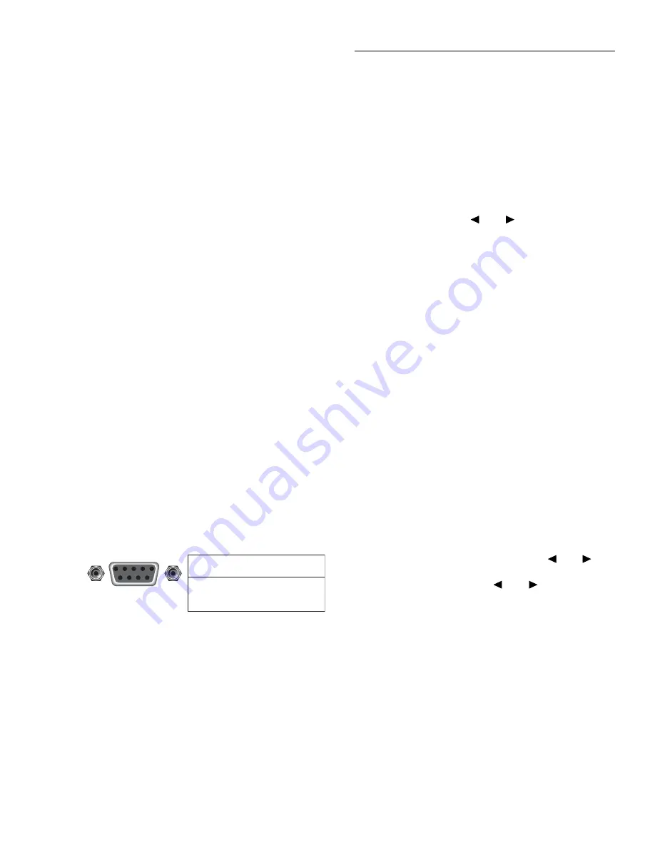
Figure 3-4
RS-232 interface connector
Rear Panel Connector
2 Transmitted Data (Tx)
3 Received Data (Rx)
5 Signal Ground (Gnd)
Pin
Number
Designation
5 4 3 2 1
9 8 7 6
RS232
lers are also given a primary address, so do not use that
address either. Most frequently, controller addresses are 0 or
21, but you should consult the controller's instruction manual
for details. Whatever primary address you choose, you must
make certain that it corresponds with the value specified as
part of the controller's programming language.
To check the present primary address or to change to a new
one, perform the following procedure:
1. Display the MAIN MENU by pressing the MENU key.
2. Use the cursor keys (
and
) to place the cursor on
COMMUNICATION and press ENTER. The COM-
MUNICATIONS SETUP menu will be displayed.
3. Place the cursor on GPIB and press ENTER.
NOTE
If you are switching from the RS-232 in-
terface to the GPIB interface, the instru-
ment will reset to the power-on defaults. In
this case, you will have to repeat steps 1, 2
and 3 to display the GPIB/PRINTER SET-
UP menu.
4. Place the cursor on ADDRESSABLE and press EN-
TER. The ADDRESSABLE GPIB menu will be dis-
played.
5. Place the cursor on ADDRESS and press ENTER.
6. The current primary address of the instrument will be
displayed. For example, if the instrument is set to prima-
ry address 27, the following message will be displayed:
ADDRESS = 27 (0-30)
7. To retain the displayed address, press EXIT four times
to return the instrument to the measurement display
state.
8. To change the primary address, use the
and
keys
and the RANGE
▲
and
▼
keys to display the new ad-
dress value (0 to 30). The
and
keys control cur-
sor position and the
▲
and
▼
keys increment and
decrement the selected digit.
9. With the desired address value displayed, press ENTER.
The address will be stored in non-volatile memory. That
is, it will not be lost when the instrument is turned off.
10. Press EXIT three times to return to the measurement
display state.
NOTE
Each device on the bus must have a unique
primary address. Failure to observe this
precaution will probably result in erratic
bus operation.


