


32
Intel
®
Modular Server System Service Guide
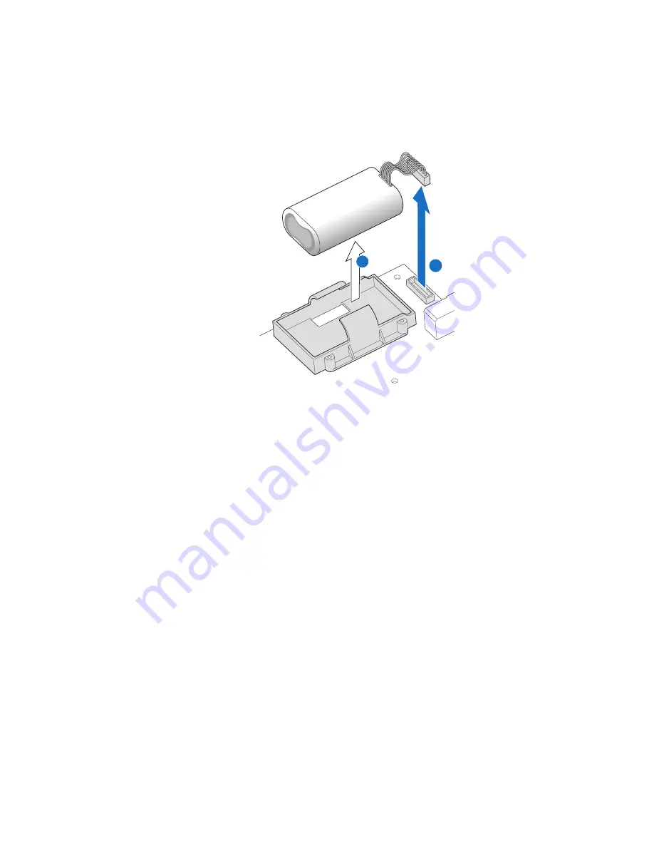
6. Disconnect the battery cable from the battery connector on the printed circuit board
(see letter “A” in
Figure 19
). Remove the battery from the black plastic battery holder
(see letter “B” in
Figure 19
).
Figure 19. Removing Backup Battery
7. Align notches in the top cover with corresponding tabs in the storage control module.
Slide the top cover forward to close.
8. Secure the top cover to the storage control module with the two screws previously
removed.
9. Re-install the storage control module in the server system. For instructions, see
“Installing a Storage Control Module” on page 26
.
Installing and Removing a Power Supply Module
The Intel
®
Modular Server System MFSYS25/MFSYS35 ships with two power supply
modules pre-installed. A single power supply is suitable to support the power requirement
for the chassis, including fan modules, storage control module, switch module, storage
bay, and a single compute module. Additional power modules are required as the number
of installed compute modules increases.
Note:
One power supply module supports one compute module plus all other modules in the
system.
Two power supply modules support two to three compute modules (in any slot) plus all
other modules in the system.
B
A
AF002461
Summary of Contents for MFSYS25V2
Page 4: ...iv Intel Modular Server System Service Guide ...
Page 14: ...xiv Intel Modular Server System Service Guide ...
Page 16: ...xvi Intel Modular Server System Service Guide ...
Page 82: ...66 Intel Modular Server System Service Guide ...
Page 137: ...Intel Modular Server System Service Guide 121 Figure 71 Storage Layout Graphical View ...
Page 144: ...128 Intel Modular Server System Service Guide Figure 79 System Information Report ...
Page 172: ...156 Intel Modular Server System Service Guide ...
Page 186: ...170 Intel Modular Server System Service Guide ...
Page 198: ...182 Intel Modular Server System Service Guide ...