3-22
Chapter 3
Installing the UPS
Examples of PowerTrust Connections in a System
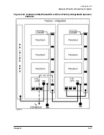
Example 2: Single Expansion Cabinet System
(Factory-Integrated)
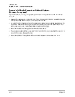
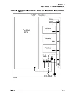
Figure 3-12 shows a factory-integrated system with one expansion cabinet. Note these
features:
• One switchless Power Distribution Unit (PDU) is installed. This PDU receives its power
from the IEC320 C19 connector on the PowerTrust UPS.
• All peripherals in the cabinet and the expansion cabinet fan are being powered via the
UPS PDU. Note that powering all expansion cabinet peripherals in this manner may
not be possible in every case due to power loading restrictions.
• The system console is being powered from the UPS PDU.
• The expansion cabinet fan is powered from the UPS PDU, to ensure that the cabinet is
cooled in the event of power failure.
• The system SPU is being powered from the 30A output of the PowerTrust UPS.
Summary of Contents for PowerTrust A3589A
Page 7: ...Contents Contents 5 ...
Page 8: ...Contents 6 Contents ...
Page 10: ...Contents 8 Figures ...
Page 12: ...Contents 10 Tables ...
Page 14: ...2 ...
Page 20: ...Preface 8 ...
Page 22: ...Preface 10 ...
Page 52: ...1 30 Chapter1 Overview Specifications Figure 1 8 UPS Input Voltage Transfer Points ...
Page 56: ...1 34 Chapter1 Overview UPS Modes Figure 1 10 Simplified UPS 5 5 kVA UPS Block Diagram ...
Page 62: ...1 40 Chapter1 Overview Support Information ...
Page 76: ...2 14 Chapter2 Unpacking and Inspecting Shipping and Storage Requirements ...
Page 104: ...3 28 Chapter3 Installing the UPS Examples of PowerTrust Connections in a System ...
Page 116: ...5 4 Chapter5 Verification Procedures Load Testing ...
Page 148: ...7 6 Chapter7 Cleaning and Maintenance Exchanging Batteries Fan ...
Page 190: ...A 42 AppendixA HP UX UPS Monitor Error Messages Log Only Messages ...
Page 218: ...C 8 AppendixC Configuring the OS for the PowerTrust UPS Power Failing the UPS ...

