Chapter 6
6-25
Troubleshooting
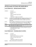
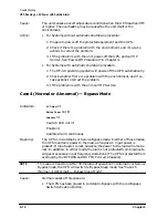
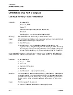
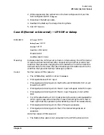
UPS Halted (Has No AC Output)
Attention
lit
Caution LED not lit
Enable not lit
Audible Alarm: continuous
Meaning:
This case indicates that the UPS internal circuits have become dormant
after 30 minutes of operation in Automatic or Service Bypass mode (see
“Case 4 (Normal or Abnormal) — Bypass Mode”). The UPS enters this
state to minimize the rate of discharge of its batteries, since its battery
charging circuits are not functional while in Bypass mode.
Cause:
Normal causes of this case are:
• The UPS has been placed in Service Bypass for more than 30 minutes.
• The red Bypass Switch Activation Button of the UPS was depressed
(manually forcing the UPS in Automatic Bypass mode) at least 30
minutes earlier.
Abnormal causes of this case are:
• The UPS microprocessor detected a UPS internal failure and placed the
unit in Automatic Bypass mode. 30 minutes later, the UPS entered this
case.
• The Battery Box cable is not connected to the UPS Electronics Unit.
• The Battery Precharge Shorting Plate is not properly installed onto the
corresponding connector blades of the Electronics Unit.
• The UPS batteries are deeply discharged or dead.
Action:
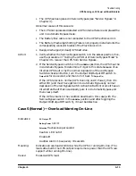
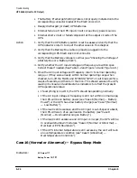
1. Verify whether the Service Bypass switch is in the
Bypass
position. If so,
use the procedure in “Placing the UPS in Service Bypass Mode” in
Chapter 4 to recover the UPS from Service Bypass mode.
2. If the Service Bypass switch is in the
NORMAL
position, the UPS is in
Automatic Bypass Sleep mode. To determine if the UPS is in this
condition because of an internal UPS fault or because the red Bypass
Switch Activation Button was pressed, follow this procedure:
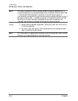
a. Place the UPS in Service Bypass mode using the procedure outlined
“Placing the UPS in Service Bypass Mode” in Chapter 4. This action
prevents dropping the UPS output voltage during the rest of this
procedure.
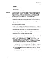
b. Set the UPS/Battery switch to
DISABLE
for one second, and then set it
back to
ENABLE
.
c. Set the Output On/Output Off switch to
Output Off
for one second, and
then set it back to
Output On
.
Summary of Contents for PowerTrust A3589A
Page 7: ...Contents Contents 5 ...
Page 8: ...Contents 6 Contents ...
Page 10: ...Contents 8 Figures ...
Page 12: ...Contents 10 Tables ...
Page 14: ...2 ...
Page 20: ...Preface 8 ...
Page 22: ...Preface 10 ...
Page 52: ...1 30 Chapter1 Overview Specifications Figure 1 8 UPS Input Voltage Transfer Points ...
Page 56: ...1 34 Chapter1 Overview UPS Modes Figure 1 10 Simplified UPS 5 5 kVA UPS Block Diagram ...
Page 62: ...1 40 Chapter1 Overview Support Information ...
Page 76: ...2 14 Chapter2 Unpacking and Inspecting Shipping and Storage Requirements ...
Page 104: ...3 28 Chapter3 Installing the UPS Examples of PowerTrust Connections in a System ...
Page 116: ...5 4 Chapter5 Verification Procedures Load Testing ...
Page 148: ...7 6 Chapter7 Cleaning and Maintenance Exchanging Batteries Fan ...
Page 190: ...A 42 AppendixA HP UX UPS Monitor Error Messages Log Only Messages ...
Page 218: ...C 8 AppendixC Configuring the OS for the PowerTrust UPS Power Failing the UPS ...

