


Chapter 1
1-13
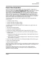
Overview
Control Panel Switches and Indicators
WARNING
Turning off the MAIN INPUT circuit breaker does NOT turn off the
PowerTrust UPS! Instead, the UPS goes to the "on-battery" state of
operation. See Chapter 4, “Power-On/Power-Off Procedures.”.
7
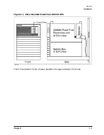
Battery
Connector
The Battery Box is connected to the Electronics Unit using a battery
cable. The cable from the Battery Box is plugged into a connector at the
bottom of the Electronics Unit. For information on how to connect the
Electronics Unit to the Battery Box, refer to “Connecting the Battery
Box Cable to the Electronics Unit” in Chapter 3.
8
Output Circuit
Breakers
When an Output circuit breaker activates, it shuts off the AC voltage to
the corresponding output receptacle.
There are four output circuit breakers that protect the UPS from
overcurrent conditions.
The first three output circuit breakers (marked
OUTLET 1, OUTLET 2
and
OUTLET 3
) provide overcurrent protection for the IEC320 C19 outlets
(see
2
in Figure 1-3). The circuit breaker marked
OUTLET 4
provides
overcurrent protection for the output receptacle (see
1
in Figure 1-3).
The AC coming out of the corresponding output receptacle remains off
until the cause of the overcurrent is corrected, the circuit breaker is
reset, and, depending on the severity of the problem, the UPS/BATTERY
switch is cycled (turned off then back on). This restores the UPS to
normal operation.
Figure 1-3 shows the AC power input for the 30A Service Bypass Unit.
For information on the 40A Service Bypass Unit, refer to Appendix E,
“40A Service Bypass Unit: Specifications and Procedures.”
9
Input Circuit
Breakers
The input circuit breaker marked
BYPASS
shuts off the AC input to the
Service Bypass Unit, Electronics Unit, and the system load in the event
of an overload (overcurrent condition). If the UPS is in Automatic or
Service Bypass mode when the overload occurs, this breaker will trip
and all AC power to the attached equipment is lost.
The input circuit breaker marked
MAIN
protects the UPS and the
protected equipment from overcurrent conditions when the UPS is
operating normally from the AC line; that is, when the UPS is neither in
Bypass mode nor on battery.
The UPS remains in this condition until the cause of the overcurrent is
corrected, the circuit breaker is reset, and, depending on the severity of
the problem, the UPS/BATTERY switch is cycled (turned off then back
on). This restores the UPS to normal operation.
Summary of Contents for PowerTrust A3589A
Page 7: ...Contents Contents 5 ...
Page 8: ...Contents 6 Contents ...
Page 10: ...Contents 8 Figures ...
Page 12: ...Contents 10 Tables ...
Page 14: ...2 ...
Page 20: ...Preface 8 ...
Page 22: ...Preface 10 ...
Page 52: ...1 30 Chapter1 Overview Specifications Figure 1 8 UPS Input Voltage Transfer Points ...
Page 56: ...1 34 Chapter1 Overview UPS Modes Figure 1 10 Simplified UPS 5 5 kVA UPS Block Diagram ...
Page 62: ...1 40 Chapter1 Overview Support Information ...
Page 76: ...2 14 Chapter2 Unpacking and Inspecting Shipping and Storage Requirements ...
Page 104: ...3 28 Chapter3 Installing the UPS Examples of PowerTrust Connections in a System ...
Page 116: ...5 4 Chapter5 Verification Procedures Load Testing ...
Page 148: ...7 6 Chapter7 Cleaning and Maintenance Exchanging Batteries Fan ...
Page 190: ...A 42 AppendixA HP UX UPS Monitor Error Messages Log Only Messages ...
Page 218: ...C 8 AppendixC Configuring the OS for the PowerTrust UPS Power Failing the UPS ...