


6-8
Chapter 6
Troubleshooting
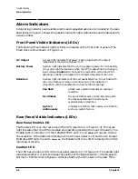
Alarm Indicators
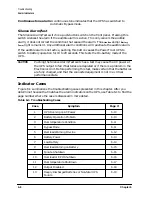
Continuous tone alarm A continuous tone indicates that the UPS has switched to
Automatic Bypass mode.
Silence Alarm/Test
The Silence Alarm/Test switch is a push-button switch on the front panel. Pressing this
switch silences the alarm if the audible alarm is active. This only cancels the audible
alarm, it does not correct the condition that caused the alarm. The
Attention
and/or
Battery
Power
light remains lit. Any additional alarm conditions will reactivate the audible alarm.
If the audible alarm is not active, pushing this button causes the PowerTrust UPS to
switch to battery operation for 10 to 20 seconds. This tests the On-battery mode of the
UPS.
CAUTION
Pushing the Silence Alarm/Test switch as a test may cause the AC power at
the UPS output to fail if batteries are depleted or if there is a problem in the
Electronics Unit. Before performing this test, make certain that the batteries
are fully charged, and that the connected equipment is not in a critical
performance state.
Indicator Cases
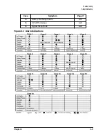
Figure 6-1 summarizes the troubleshooting cases presented in this chapter. After you
determine the case that matches the alarm indicators on the UPS, use Table 6-1 to find the
page number where the case is discussed in more detail.
Table 6-1 Troubleshooting Cases
Case
Symptom
Page #
1
UPS Running on AC Power
6-10
2
Battery Operation Problem
6-10
3
Overtemperature Condition
6-11
4
Bypass Mode
6-11
5
Overload Warning On-Line
6-12
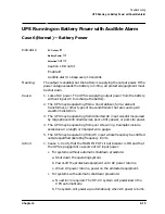
6
Battery Power
6-13
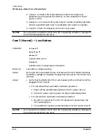
7
Low Battery
6-14
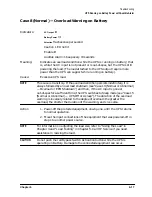
8
Overload Warning on Battery
6-15
9
Failure Shutdown
6-16
10
Overload or EPO Shutdown
6-16
11
Overtemperature Shutdown
6-17
12
Output Disabled
6-18
13
Deeply Discharged Batteries or Non-fatal UPS
Failure
6-19
Summary of Contents for PowerTrust A3589A
Page 7: ...Contents Contents 5 ...
Page 8: ...Contents 6 Contents ...
Page 10: ...Contents 8 Figures ...
Page 12: ...Contents 10 Tables ...
Page 14: ...2 ...
Page 20: ...Preface 8 ...
Page 22: ...Preface 10 ...
Page 52: ...1 30 Chapter1 Overview Specifications Figure 1 8 UPS Input Voltage Transfer Points ...
Page 56: ...1 34 Chapter1 Overview UPS Modes Figure 1 10 Simplified UPS 5 5 kVA UPS Block Diagram ...
Page 62: ...1 40 Chapter1 Overview Support Information ...
Page 76: ...2 14 Chapter2 Unpacking and Inspecting Shipping and Storage Requirements ...
Page 104: ...3 28 Chapter3 Installing the UPS Examples of PowerTrust Connections in a System ...
Page 116: ...5 4 Chapter5 Verification Procedures Load Testing ...
Page 148: ...7 6 Chapter7 Cleaning and Maintenance Exchanging Batteries Fan ...
Page 190: ...A 42 AppendixA HP UX UPS Monitor Error Messages Log Only Messages ...
Page 218: ...C 8 AppendixC Configuring the OS for the PowerTrust UPS Power Failing the UPS ...