1-8
Chapter 1
Overview
Electronics Unit and Bypass Operations
Electronics Unit and Bypass Operations
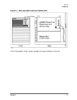
Under normal operating conditions the Electronics Unit provides AC power through the
AC power input cable of the Service Bypass Unit. This operating mode is called
On-line
mode.
If the Electronics Unit malfunctions, however, the Electronics Unit still redirects the
AC input power to the output receptacles in order to maintain AC power to the system
load. This feature is called
Automatic Bypass mode.
Another operating mode,
Service Bypass
mode,
allows the Electronics Unit and Battery Box to be serviced without disrupting power
to the connected equipment. To enter Service Bypass mode, the red Bypass button must be
pressed and the Service Bypass switch must be manually set to
BYPASS
. In Service Bypass
mode, the AC input bypasses the Electronics Unit and is sent directly to the output
receptacles.
WARNING
The Electronics Unit must be serviced only while the UPS is in
Service Bypass mode. Replacement of the Electronics Unit with the
UPS in Automatic Bypass mode will result in loss of power to the
connected equipment.
Timed Power-Off/Power-On
PowerTrust UPS units installed on HP-UX systems also support a timed
power-off/power-on facility. This allows you to power down the HP-UX system and have the
PowerTrust UPS restore power to the system at a predetermined time. See the
power_onoff(1M)
man page for more information.
Currently, MPE/iX does not support the timed power-off/power-on facility.
Summary of Contents for PowerTrust A3589A
Page 7: ...Contents Contents 5 ...
Page 8: ...Contents 6 Contents ...
Page 10: ...Contents 8 Figures ...
Page 12: ...Contents 10 Tables ...
Page 14: ...2 ...
Page 20: ...Preface 8 ...
Page 22: ...Preface 10 ...
Page 52: ...1 30 Chapter1 Overview Specifications Figure 1 8 UPS Input Voltage Transfer Points ...
Page 56: ...1 34 Chapter1 Overview UPS Modes Figure 1 10 Simplified UPS 5 5 kVA UPS Block Diagram ...
Page 62: ...1 40 Chapter1 Overview Support Information ...
Page 76: ...2 14 Chapter2 Unpacking and Inspecting Shipping and Storage Requirements ...
Page 104: ...3 28 Chapter3 Installing the UPS Examples of PowerTrust Connections in a System ...
Page 116: ...5 4 Chapter5 Verification Procedures Load Testing ...
Page 148: ...7 6 Chapter7 Cleaning and Maintenance Exchanging Batteries Fan ...
Page 190: ...A 42 AppendixA HP UX UPS Monitor Error Messages Log Only Messages ...
Page 218: ...C 8 AppendixC Configuring the OS for the PowerTrust UPS Power Failing the UPS ...


