Appendix C
C-5
Configuring the OS for the PowerTrust UPS
Configuring MPE/iX for the PowerTrust UPS
Configuring MPE/iX for the PowerTrust UPS
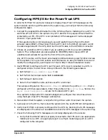
In order for MPE/iX 5.0 and later releases to display PowerTrust UPS messages on the
system console and to log UPS events to the system log, you must perform the following
configuration tasks:
1. Connect the supplied RS-232 cable from the UPS to a 25-wire modem port on a DTC for
each PowerTrust UPS in the system. Any DTC used for this purpose should itself be
protected by a UPS; if the DTC is not protected, UPS messages will not be displayed
when AC input power fails.
If the supplied cable is not long enough, use a straight-through 25-wire RS-232-C
extender cable (3062C, 25 feet long) from the DTC port to the DB-25 connector end of
the cable supplied with the UPS, and then the UPS cable to the UPS DB-9 connector.
2. Choose an available LDEV number if you are adding a UPS to an existing 990/992
System. The configuration groups supplied for 991/995 Systems leave LDEV 22
undefined and suitable for use for the first UPS on the system.
Any LDEV used by a UPS should not already be defined as being used for other devices
for the system. For log on instructions and information on using SYSGEN to view and
modify the configuration, see Chapter 2 of the CS 99x/T-Class Installation Guide.
3. Use NMMGR to configure the DTC port for each UPS. A port connected to a UPS is
configured similar to a terminal. Use a profile with the following parameters:
a. Set the field
Allow :HELLO logon?
to
N
.
b. Set the first device class name field to
HPUPSDEV
.
c. Set the baud rate to
1200
.
d. Set all other fields the same as those used for a terminal.
The sample configuration file
NMSAMP1.PUB.SYS
contains the profile
UP10D12
that is
configured with these parameters. Enter this profile in the
Profile Name
field on the
Async Card Configuration
screen for the desired DTC port.
On a system configured for PC-based management, configure the correct baud rate
using the Open View DTC Manager workstation.
4. Make certain that the system is not performing critical work. Shut down the system.
5. Cycle power to the DTCs, then reboot the system with the new NMMGR configuration.
6. Verify that MPE/iX is properly configured for the UPS by checking that UPS messages
are displayed on the console. Use
LOGTOOL
to check for UPS messages in the system log.
7. Check the following if UPS messages are not being displayed on the console:
a. Verify that the RS-232 cable is properly connected to the UPS and to an appropriate
modem port on a DTC. An appropriate port is a 25-pin modem-type port on a DTC
configured to the computer.
Summary of Contents for PowerTrust A3589A
Page 7: ...Contents Contents 5 ...
Page 8: ...Contents 6 Contents ...
Page 10: ...Contents 8 Figures ...
Page 12: ...Contents 10 Tables ...
Page 14: ...2 ...
Page 20: ...Preface 8 ...
Page 22: ...Preface 10 ...
Page 52: ...1 30 Chapter1 Overview Specifications Figure 1 8 UPS Input Voltage Transfer Points ...
Page 56: ...1 34 Chapter1 Overview UPS Modes Figure 1 10 Simplified UPS 5 5 kVA UPS Block Diagram ...
Page 62: ...1 40 Chapter1 Overview Support Information ...
Page 76: ...2 14 Chapter2 Unpacking and Inspecting Shipping and Storage Requirements ...
Page 104: ...3 28 Chapter3 Installing the UPS Examples of PowerTrust Connections in a System ...
Page 116: ...5 4 Chapter5 Verification Procedures Load Testing ...
Page 148: ...7 6 Chapter7 Cleaning and Maintenance Exchanging Batteries Fan ...
Page 190: ...A 42 AppendixA HP UX UPS Monitor Error Messages Log Only Messages ...
Page 218: ...C 8 AppendixC Configuring the OS for the PowerTrust UPS Power Failing the UPS ...


