Chapter 3
3-17
Installing the UPS
Cabling Connections
Cabling Connections
Connecting Equipment to the PowerTrust UPS (with 30A
Service Bypass Unit Only)
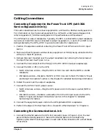
This section describes how to connect equipment to a UPS with a 30A Service Bypass Unit.
For information on how to connect equipment to a UPS with a 40A Service Bypass Unit,
refer to Appendix E, “40A Service Bypass Unit: Specifications and Procedures.”
The UPS has four output receptacles. Typically, the SPU is connected to output receptacle
4 and one or more PDU(s) are connected to output receptacles 1, 2, and 3. If an SPU is not
being protected by the UPS, a PDU may also be connected to receptacle 4.
1. Position the expansion cabinet containing the PowerTrust UPS close to the AC input
source.
2. Make sure that the power switches of any equipment or PDU(s) being connected to the
UPS are in the OFF position.
3. Remove the cover mounted over the output receptacles by removing the two screws at
the top of the cover. See Figure 1-3,
14
.
4. Connect the line cord(s) from the PDU(s) to the IEC 320 C19 output receptacle(s).
5. Connect the SPU or PDU to the UPS:
• North American version—Plug the SPU or PDU line cord into the NEMA L6-30R
receptacle.
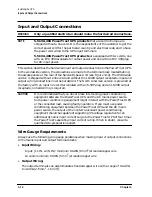
• Worldwide version—Hardwire the SPU or PDU line cord to the UPS. Refer to “Input
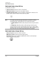
and Output Connections” earlier in this chapter for detailed hardwiring information.
6. Install the cover over the output receptacles.
7. Connect the UPS to the AC power source:
• North American version—Plug the UPS power cord into the source outlet (NEMA
6-50P).
• Worldwide version—Hardwire a connection from the AC input source to the UPS.
Refer to “Input and Output Connections” earlier in this chapter for detailed
hardwiring information.
8. Connect the equipment power cords to the UPS-protected PDU receptacles.
9. Perform the steps in “Initial Power-On or Power-On After Shutdown” in Chapter 4.
Connecting the Communications Link
1. Connect the RS-232 cable to the UPS Port connector (see
6
in Figure 1-3) on the rear
panel of the Service Bypass Unit. Secure the RS-232 cable to the connector by
tightening the small mounting screws on each side of the connector with a small blade
screw driver.
Summary of Contents for PowerTrust A3589A
Page 7: ...Contents Contents 5 ...
Page 8: ...Contents 6 Contents ...
Page 10: ...Contents 8 Figures ...
Page 12: ...Contents 10 Tables ...
Page 14: ...2 ...
Page 20: ...Preface 8 ...
Page 22: ...Preface 10 ...
Page 52: ...1 30 Chapter1 Overview Specifications Figure 1 8 UPS Input Voltage Transfer Points ...
Page 56: ...1 34 Chapter1 Overview UPS Modes Figure 1 10 Simplified UPS 5 5 kVA UPS Block Diagram ...
Page 62: ...1 40 Chapter1 Overview Support Information ...
Page 76: ...2 14 Chapter2 Unpacking and Inspecting Shipping and Storage Requirements ...
Page 104: ...3 28 Chapter3 Installing the UPS Examples of PowerTrust Connections in a System ...
Page 116: ...5 4 Chapter5 Verification Procedures Load Testing ...
Page 148: ...7 6 Chapter7 Cleaning and Maintenance Exchanging Batteries Fan ...
Page 190: ...A 42 AppendixA HP UX UPS Monitor Error Messages Log Only Messages ...
Page 218: ...C 8 AppendixC Configuring the OS for the PowerTrust UPS Power Failing the UPS ...

