System Testing and Verification
Testing the Precision Platform operation
4.
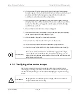
Confirm that the crash switch LED (DS21 cable end termination
board) is green. If not, check that all crash switches are in the closed
position and that both emergency stop switches (mushroom
switches at each end) are in the out position.
5.
Check that the motor enable key switch is in the enable position
(display that shows
EF
is disabled). The motor enable key switch is
located on the cable-end support column adjacent to the Sample
and Reference switch.
6.
Ensure that the circuit breaker has not tripped.
7.
Check that the motor controller is at the current limit.
CL
displays
in the motor controller LED display if it is.
8.
Check contact outputs for Scan and Direction.
9.
Use hardware write function to try to scan the heads.
10.
Verify that the scanner software variables are set correctly.
11.
Are the Comp/Man and Host/Shop mode switches set correctly?
WARNING
:
Do not scan in the maintenance mode! This engages the caliper
sensor offsheet and will break the sheet. Before startup, scan on
static sheet with unique edge streaks so that profile orientation and
edge object can be tested.
4.2.4. Verifying drive motor torque
Set the drive motor torque to the point at which it is possible to stop
scanning by exerting a moderate manual force on the heads. The torque
can be tested by starting a scan and then attempting to stop the moving
heads.
!
CAUTION
:
Be prepared in case the torque is too high – allow an avenue of
escape if the heads do not stop.
P/N 6510020208
10/4/07
4-9
Summary of Contents for 4022
Page 1: ...Precision Platform 4022 Scanner System Manual 6510020208 ...
Page 2: ......
Page 3: ...Precision Platform 4022 Scanner October 2007 ...
Page 22: ......
Page 72: ......
Page 94: ......
Page 126: ......
Page 162: ......
Page 170: ......
Page 234: ......
Page 239: ...Glossary p n 6510020208 10 18 07 11 5 VIO Virtual Input Output ...

