Scanner Maintenance
Head Separation Clutch
9.7.2. Clutch pin replacement
9.7.2.1.
Removing the Clutch Assembly
i
N
OTE
:
Make sure there are spares for all of the items in this
assembly before proceeding, especially the retaining
rings, springs, Lubriplate and clutch pins (check the
spare parts list and scanner assembly drawings).
1.
Turn off the Motor Power keyswitch.
WARNING
:
Injury can occur. Turn off the Motor Power keyswitch
before removing the beam covers.
2.
Remove the cable end beam covers and loosen the head drive belts
as described in Subsection 9.6.3.
3.
Remove the AC motor belt from the large pulley.
4.
Remove the clutch assembly by removing the ¼"-20 screws.
9.7.2.2. Clutch
disassembly
1.
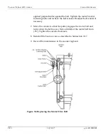
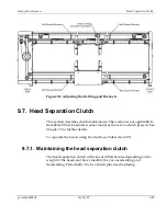
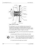
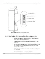
See Figure 9-7 showing the clutch assembly. Also see drawings
shipped with your scanner for clutch assembly details.
2.
Remove the clutch pin retaining rings and clutch bar.
3.
Remove the retaining ring on the large pulley end of the shaft.
4.
Remove the large pulley and outer 2.8 inch pulley, using a gear
puller if necessary.
5.
Once the large pulley and the outer 2.8 inch pulleys are removed,
check the clutch pins for wear. The taper on the pins should not be
grooved or dented.
p/n 6510020208
10/18/07
9-31
Summary of Contents for 4022
Page 1: ...Precision Platform 4022 Scanner System Manual 6510020208 ...
Page 2: ......
Page 3: ...Precision Platform 4022 Scanner October 2007 ...
Page 22: ......
Page 72: ......
Page 94: ......
Page 126: ......
Page 162: ......
Page 170: ......
Page 234: ......
Page 239: ...Glossary p n 6510020208 10 18 07 11 5 VIO Virtual Input Output ...

