Precision Platform 4022 Scanner
Installation
10/4/07
p/n:
6510020208
3-14
Refer to the Scanner Installation Drawings.
3.9.1.
Connecting external cooling fluid to the
Precision Platform
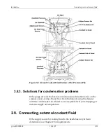
External fluid sources connect to the scanner through hoses connected to
the air and coolant manifold at the cable end support. Plumbing for both
the fluid source and the drain must be provided, at approximately floor
level, to approximately 1.5 m (5 ft) from the planned location for the cable
end support.
During installation, hoses from the Honeywell scanner installation kit can
be used to attach the mill water open loop or the chiller closed loop to the
hose barbs on the manifold, which is located near the bottom of the cable
end support.
Refer to the Scanner Installation Drawings.
3.9.2. Installing a water-to-water heat exchanger
The procedure for installing a Honeywell water-to-water heat exchanger
cooling system is explained in this section. The installation drawing shows
the front and bottom views of the water-to-water exchanger unit,
including the reservoir level indicator, temperature gauge, pressure
gauge, and the in and out mill water plumbing connections.
The manual provided with the exchanger shows top and side views of the
exchanger unit. In the top view, note the setpoint adjustment valve and
hinged lid to the exchanger unit reservoir tank.
To install a Honeywell water-to-water exchanger cooling system:
1.
Mount the unit next to the scanner (no farther away from the
scanner than 6m [20 ft]).
2.
For a retrofit installation, cut 10mm (3/8-inch) hose going to the
scanner and attach it to the water in and out connections on the
exchanger unit.
Summary of Contents for 4022
Page 1: ...Precision Platform 4022 Scanner System Manual 6510020208 ...
Page 2: ......
Page 3: ...Precision Platform 4022 Scanner October 2007 ...
Page 22: ......
Page 72: ......
Page 94: ......
Page 126: ......
Page 162: ......
Page 170: ......
Page 234: ......
Page 239: ...Glossary p n 6510020208 10 18 07 11 5 VIO Virtual Input Output ...


