background image

REAR WHEEL/BRAKE/SUSPENSION

14-14

SWING ARM

DISMANTLING

Remove the following components: Silencer (page 2-5) 

Rear wheel (page 14-3) 

Bolt and nut lower damper (page 14-12)

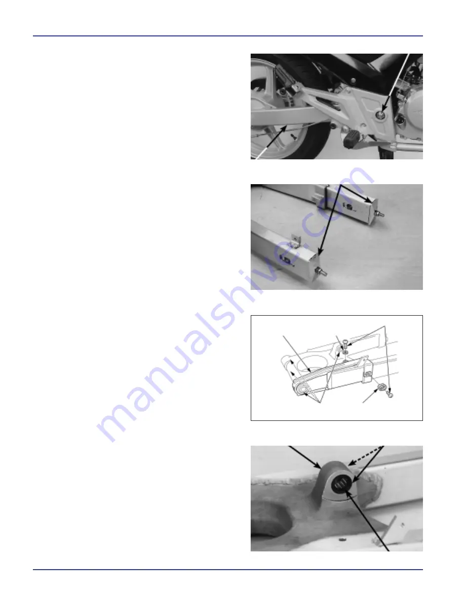
Remove the nut pivot swing arm. 

From the left side, remove the bolt pivot and swing arm.

DISMANTLED

Inspect the guide to the drive chain with regard to 
wear or damage. 

Remove the adjusters in the drive chain.

SWING ARM

BOLT/NUT PIVOT

Remove the two screws, the spacer of the guide and the 
guide to the drive chain. 

Remove the spacers of pivots swing arm.

Remove the coveralls and the bearing of needles of the
articulation of the damper.

BALL NEEDLES

ARTICULATION OF
THE DAMPER 

DUST COVERS

ADJUSTERS IN THE DRIVE CHAIN

CBX250

CHAIN
GUIDE 

WASHER

BOLTS

SPACERS joints 

SPACER OF
THE GUIDE

Summary of Contents for 2010 CBF 250

Page 1: ...WORKSHOP MANUAL...

Page 2: ...ctions 1 and 3 are applicable to the whole motorcycle The Section 2 present procedures of dis assembly installation of components that can be necessary to make the services described in the following...

Page 3: ...tion on the basis of lithium NGLI No 2 Or equivalent Use grease of carbon disulphide molybdenum containing more than 3 percent of car bon disulphide of molybdenum LITHIUM No 2 Or equivalent Use pulp o...

Page 4: ...Use protective clothing and protective mask In the event that the electrolyte comes into contact with the skin wash with plenty of water In the event that the electrolyte comes into contact with the e...

Page 5: ...g British The use of tools and fixers incorrect can damage the motorcycle 4 Install gaskets rings o smugglers hendidos and plates of locks new when carrying out the assembly 5 By tightening bolts scre...

Page 6: ...eering column The number of identification of the carburetor is recorded in the left side of the carburetor according to the illustration The number of series of the engine is recorded in the left sid...

Page 7: ...s PIRELLI MT75 Front Brake A single disk hydraulic Rear Brake A drum mechanical type with shoe simple expansion Inclination of the axle of pivot 25 5 Long progress 100 mm Capacity of fuel tank 16 5 l...

Page 8: ...geared Primary Reduction 3 100 62 20 Final Reduction 2 846 37 13 Gear Ratio 1 2 769 36 13 2 1 882 32 17 3 1 333 28 21 4 1 083 26 24 5 0 923 24 26 6 0 814 22 27 System of changing gears Return System...

Page 9: ...s internal and external 0 15 0 20 Slack between the external rotor and the body of the pump 0 15 0 21 0 25 Slack between the rotors and flank of the body of the pump 0 02 0 08 0 12 LUBRICATION SYSTEM...

Page 10: ...oil 0 020 0 062 0 10 Valves and valve Valve slack ADM 0 12 guides ESC 0 15 External Diameter of body of the valve ADM 4 975 4 990 4 96 ESC 4 955 4 970 4 94 Internal diameter of the guide to the valve...

Page 11: ...07 Slack between the crank and the cotter pin 0 016 0 040 0 09 Slack between the ring Ring upper 0 015 0 050 0 12 of piston and the slot Ring 0 015 0 050 0 12 secondary Opening of the limbs of os Ring...

Page 12: ...of the main axis Al M5 19 959 19 980 19 91 D E of the countershaft Al C1 17 966 17 984 17 91 Al C2 C4 21 959 21 980 21 91 Slack between gear and the hub 0 020 0 062 0 10 Slack between gear and the sp...

Page 13: ...2 0 Counterweight to balance Max 60 g Fork Free length of spring 434 4 428 4 Eccentricity of the tube of the fork 0 20 Fluid recommended Fork fluid ATF Fluid Level 145 Capacity of fluid 296 2 5 cm3 B...

Page 14: ...cylinder 10 957 10 984 10 945 D I The cylinder of the clamp 25 400 25 450 25 460 D E The piston caliper 25 318 25 368 25 31 BATTERY CHARGING SYSTEM Item Specifications Battery Capacity 12 V 6 Ah Leaka...

Page 15: ...YSTEM SYSTEM OF ELECTRIC Starter Units mm LIGHTS INSTRUMENTS Switches Item Value Service Limit Over the motor brushes of start 12 5 8 5 Item Specifications Lights Light High 12 V 35 W Low 12 V 35 W Re...

Page 16: ...e cylinder head 2 8 12 1 2 Other fixers Bolt to the plate of cams of changing gears 1 6 12 1 2 Note 2 Bolt of terminal breaker of deadlock 1 4 2 0 2 Body breaker deadlock 1 10 12 1 2 Bolt to the plate...

Page 17: ...9 5 9 Note 9 Bolt of disk on the front brake 5 8 42 4 2 Note 10 Rear Wheel Brake Suspension Nut of the rear axle 1 16 88 8 8 Note 9 Nut of the crown of transmission 6 10 64 6 4 Note 9 Nut superior of...

Page 18: ...ctor of the rotor 07733 0020001 10 Bar of extension of extractor 07716 0020500 10 Driving force behind the checkpoint of the fork 07747 0010100 13 Accessory of driver catch of the fork 07747 0010600 1...

Page 19: ...ty of the cylinder drive shaft of the mechanism of clutch Guide for operating the clutch surfaces of lining of the disk of clutch Thread and surface of seat of the nut of locks of the body of clutch T...

Page 20: ...ls stamps and pistons tweezers brake Pivot of the lever of front brake Silicon based grease Inside the protective rubber cord accelerator Internal Part of protective rubber cord clutch Pistons tweezer...

Page 21: ...ng WIRING OF THE SWITCHES OF THE HANDLEBARS RIGHT WIRING OF THE SWITCHES OF THE HANDLEBARS LEFT THE CABLE CHOKE CABLE CLUTCH WIRING OF LEFT INDICATOR CABLE OF THE SPEEDOMETER HOSE front brake CABLES O...

Page 22: ...GENERAL INFORMATION CBX250 WIRING OF THE Horn CABLE OF THE VALVE OF ENRICHMENT OF START IS MAIN WIRING CABLE SPARK PLUG CABLE OF THE IGNI TION COIL CABLE OF THE SPEEDOMETER...

Page 23: ...GENERAL INFORMATION 1 20 CBX250 CABLE OF THE VALVE OF ENRICHMENT OF START IS CLUTCH CABLE HOSE front brake CABLES OF THE ACCELERATOR...

Page 24: ...HMENT OF START IS CABLES BREAKER MAG NETIC START WIRING RECTIFIER REGULATOR Positive TERMIN AL OF THE BATTERY CABLE FROM THE PULSE GENERATOR POWER ALTERNATOR SWITCH DEADLOCK WIRING BREAKER OF SIDE STA...

Page 25: ...RMATION 1 22 CBX250 WIRING BREAKER OF THE LIGHT OF rear brake BREATHER TUBE CARBURETTOR CLUTCH CABLE CABLES OF THE ACCELERATOR DRAINAGE TUBE OF THE CARBURETOR DRAINAGE BREATHER TUBE FROM THE CASING OF...

Page 26: ...GENERAL INFORMATION CBX250 MAIN WIRING WIRING OF THE REAR LIGHT OF brake WIRING OF INDICATOR REAR RIGHT WIRING OF INDICATOR REAR LEFT WIRING RECTIFIER REGULATOR FUSE BOX...

Page 27: ...in the same way Still is toxic Motor Honda da Amazonian Ltd used mix settings of poor carburetor as other procedures in order to reduce the emission of carbon monoxide and hydrocarbons CONTROL SYSTEM...

Page 28: ...t Poor Performance Exhaust System deformed Flight of the exhaust Silencer obstructed The petrol gasoline is extremely flammable and explosive under certain conditions Keep out of the reach of chil dre...

Page 29: ...AR GRIP DISMANTLING Installation Remove the saddle refer to the item above Remove the two bolts of rear grip Remove the two bolts and the spring of the support for the locks of the saddle Remove the s...

Page 30: ...s DISMANTLING INSTALLATION Remove the two nuts support and the indicator rear The installation and the assembly carried out in reverse order dismantling PLATE SIDE PIT DISMANTLING Installation Remove...

Page 31: ...ers the front fenders support and the pin of the hose front brake The installation is performed in reverse order dismantling NOTE Tighten fixing bolts the front fenders and the pin of the hose of the...

Page 32: ...silencer NOTE INSTALLATION Install the whole of the exhaust pipe and the silencer Install temporarily all nuts and fixing bolts NOTE Tighten the nuts and bolts of union of the exhaust pipe to the spe...

Page 33: ...Chassis FAIRING EXHAUST SYSTEM 2 6 CBX250 NOTES...

Page 34: ...nder certain conditions Keep out of the reach of chil dren Work on a local well ventilated The presence of cigarettes flames or sparks in the local labour or where stocks petrol gasoline can cause a f...

Page 35: ...psi Back 250 kPa 2 50 kgf cm2 36 psi Tyre dimensions Front 100 80 17 52S Back 130 70 17 62S Recommended type of tyre Front PIRELLI MT75 Back PIRELLI MT75 Minimum tread depth Front Check wear indicato...

Page 36: ...18 000 Wear on the pads of the brake Check 3 000 Shoe Drum rear brake Clean 3 000 Brake system Check the operation 3 000 Switch of the light of the brake Check the operation 3 000 Direction of focus...

Page 37: ...lve of fuel and make sure that there is no leakage FUEL FILTER O Ring FUEL FILTER d Closing the valve of fuel Remove the body of fuel filter the o ring and the sieve Drain the content of the body in a...

Page 38: ...viscosity If the grip still fails to return properly replace the cables accelerator d With the engine idling turn the handlebars completely to the right and left to ensure that the idle does not alte...

Page 39: ...he box of air filter Remove the element of air fil ter Clean the element multiplied compressed air from the inside Replace if necessary Replace the element of air filter in accordance with the recomme...

Page 40: ...re indicated a mixture too rich REUSE OF THE SPARK PLUG Clean the electrodes with a brush of steel or with a cleaner of spark plugs Check the opening between the central electrodes and side using a ga...

Page 41: ...k plug new in the cylinder head After the washer ring has been settled in the accommodation of the spark plug tighten approximately 1 2 drawing more Install the noise dampening layer in the spark plug...

Page 42: ...60 and nine different thicknesses of shims available from the most narrow 1 200 mm thickness until the thicker 2 900 mm with a difference of 0 025 mm between each The shims can retain in the interior...

Page 43: ...clockwise Check again the slack valves Check the conditions of the gasket of the top of the cylinder head Replace if necessary Install the cover of the cylinder head Accurately Measuring the thickness...

Page 44: ...hole in supply without turning Remove the rod measuring and veri fy if the level of oil is among the brands of level above and below In case of the level is below or near the line of lower level servi...

Page 45: ...es into contact with the same during an extended period Although it is not likely to happen unless it is handled used oil daily it is advisable wash their hands with soap and water barely finish manip...

Page 46: ...ance with the specifications Idle speed 1 400 100 rpm Check and adjust the idle only after all other items of engine maintenance have been inspected and ad justed in accordance with the specifications...

Page 47: ...the two nuts of the adjusters in the drive chain TORQUE 21 N m 2 1 kg m Inspect again the slack in the drive chain and the free rotation of the wheel Install the stem rear brake page 14 8 CLEANING Cl...

Page 48: ...e plate of fixing the sprocket in the region of the teeth ruffles always to replace the sprocket In the event that the thickness of teeth ruffles has reached the limit of service replace the plate Che...

Page 49: ...er link installed correctly Measure the length of the smugglers of link master projected toward the outside of the plate Length DID 1 15 1 55 mm Insert the link master since the inner side of the driv...

Page 50: ...nderground After the riveting of master link make sure the area riveted with regard to cracks In case any are cracked replace the link master the rings o and the plate d Should Not be used a drive cha...

Page 51: ...of the brake the pistons of the clamp is mov ing toward the outside contributing to lower the level of fluid in the deposit In case of that pads are not eroded and the level of fluid is low inspect al...

Page 52: ...need adjustment through adjustment nut rear brake NOTE SWITCH OF THE LIGHT OF brake NOTE Setting the switch of the light of rear brake so that the light to turn at the time that the pedal is pressed...

Page 53: ...istance CLUTCH SYSTEM Check if the cable of the clutch is not bent or damaged Lubricate if necessary Measure the play free at the end of the lever of clutch Free play 10 20 mm Minor adjustments are ma...

Page 54: ...the bracket Activates the engine with the transmission in neutral Then gear a march maintaining the lever clutch pressed Move the bracket totally downwards The engine must stop at this time Must be ch...

Page 55: ...aring case observe any slack refer to Section 14 Inspect the action of rear shock compressing the rear end several times Inspect the whole of the damper with regard to leakages damage or fixers loose...

Page 56: ...s check the bearings in the rear wheel NOTE NOTE Check pressure using a pressure gauge for tires PRESSURE RECOMMENDED AND THE DIMEN SION OF THE Tires It should inspect the pressure on the tires COLD A...

Page 57: ...soil Check to see if the handlebars moves freely from one side to another In the event that the handlebars move unevenly presenting gridlock or a vertical movement inspect the bearings of the steering...

Page 58: ...MAINTENANCE CBX250 NOTES...

Page 59: ...tain information with regard to change the oil filter SPECIFICATIONS Unit mm In case of that is necessary to make services with the engine running make sure that the local work is well ventilated Neve...

Page 60: ...4 0 LUBRICATION SYSTEM CBX250 DIAGRAM OF LUBRICATION SYSTEM...

Page 61: ...struction of the filter of sieve Wear or damage to the oil pump Internal Leakage of oil Oil Level too low Oil Pressure non existent Oil Level too low Drive gears of the oil pump broken Damage in the o...

Page 62: ...ide of the casing of the engine page 9 3 Remove the gear commanded of the oil pump and the axle Remove the two tenons guide DISMANTLING Remove the ear of guide and the o ring Remove the three bolts an...

Page 63: ...and external in the casing of the oil pump Install the axle of the oil pump Measure the slack between the rotors internally and externally Service Limit 0 20 mm Measure the slack between the external...

Page 64: ...he limits of service replace the pump as a whole Service Limit 0 12 mm INSTALLATION Before the assembly clean completely all the parts removed with solvent and drain Install the rotors external and in...

Page 65: ...ears of guide and the lid of the oil pump GUIDE DOWELS Install the two tenons guide GUIDE DOWELS Install the whole of the oil pump Install the three bolts and tighten firmly BOLT Install the three bo...

Page 66: ...lid right side of the casing of the engine page 9 13 After installation supplying the engine with the oil recommended page 3 12 and make sure that there is no leakage SEIVE FILTER The drainage of eng...

Page 67: ...pe of obstruction using compressed air or water to low pressure In case of the air flow is restricted in more than 20 percent of the surface of radiation replace the radiator Inspect the radiator and...

Page 68: ...s or damage Tube of oil from the cylinder head Inspect the tubes of oil from the cylinder head with regard to obstruction cracks or damage INSTALLATION Tube of oil radiator Install the connections sup...

Page 69: ...more than a month drain the tank of the float If it leaves the fuel in the tank the jets are may obstruct hamper the start and damaging the management So that the diaphragms do not suffer damage be su...

Page 70: ...5 0 FUEL SYSTEM CBX250...

Page 71: ...Number of the carburetor VEA2A Main Pump 150 Supplier of idling 45 Initial Opening of the idle screw 2 1 4 Turns out Level of float 18 5 mm Rotation of idling 1 400 100 rpm Free Play of the grip of th...

Page 72: ...pen position Jets of air obstructed valve in the float defective Level of float too high dirty air filter Piston defective vacuum The engine stall starts with difficulty or presents idling irreg ular...

Page 73: ...eathing the air filter Loosen the screw on the tube clamp of connecting the carburetor BREATHER TUBE SCREW ON THE TUBE CLAMP Connection DEL TUBO DE CONEXI N Disconnect the breather tube from the casin...

Page 74: ...ocation of each piece of the carburetor and then install again in its original position SCREW ON THE TUBE CLAMP CARBURETOR RESONATOR CHOKE BOLT BOLT OF ACCELERATION DRAINAGE TUBE BREATHER TUBE SCREWS...

Page 75: ...ring and the needle piston vacuum Be careful not to damage the diaphragm Not push the needle piston to remove the support SUPPORT FOR THE NEEDLE Check the following The needle is not too worn down Tha...

Page 76: ...t the spring is not weakened the needle of the dia phragm is not frayed To the air ducts are not obstructed BUCKET OF FLOAT AND JETS Remove the four screws and the vial of float Remove the cover of th...

Page 77: ...f idling i Turn the idle screw toward the inside Count the number of laps until the idle screw nodding slightly Enter this data and use as a reference to reinstall the idle screw i If it is pressed ex...

Page 78: ...this may damage the body of the carburetor PARTS OF THE CARBURETTOR i Do not remove the sensor accelerator of the body of the carburetor Never use a piece of wire to clean the air ducts because this...

Page 79: ...easily If it is pressed excessively the idle screw your seat may be damaged MAIN JET IDLE JET O RING Install the plate pit VERIFICATION OF THE LEVEL OF FLOAT NOTE With the valve in the float settled...

Page 80: ...phragm valve of court of air and spring Install and maintain fixed the lid of the valve NOTE Be careful not to hold the diaphragm Install the lid and tighten the two screws Install the vial of float a...

Page 81: ...the body of the car buretor Raise of the lower part of piston with your finger to adjust the tab of the diaphragm notching the body of the carburetor Then install the compression spring and the lid of...

Page 82: ...accelerator Install adjusters in housing Install the cable clutch The screw clamp insulator and screw tube clamp of connection Install the casing for the filter of air page 5 5 Install the breather t...

Page 83: ...T OF THE ROTA TION OF IDLING d NOTE Screw driver is previously set in the factory and does not need adjustments unless it has been replaced or that the carburetor has been disassembly Hot engine until...

Page 84: ...and adjust the rotation of idle through the bolt of acceleration Idle speed 1 400 100 rpm 5 Kink or unscrew slowly the idle screw for maximum rotation of the engine 6 Adjustment again the rotation of...

Page 85: ...ves Section 7 pulse generator power Section 17 starter Motor clutch start Section 18 Cylinder piston Section 8 oil pump Section 4 To make repairs or maintenance in the following components must remove...

Page 86: ...6 0 DISMANTLING AND INSTALLING THE ENGINE CBX250 44 N m 4 4 kg m 44 N m 4 4 kg m 44 N m 4 4 kg m 44 N m 4 4 kg m 44 N m 4 4 kg m 26 N m 2 6 kg m 26 N m 2 6 kg m 26 N m 2 6 kg m...

Page 87: ...engine 26 N m 2 6 kg m Bolt nut lower front engine 44 N m 4 4 kg m Bolt nut higher rear engine 44 N m 4 4 kg m Bolts of rear support higher engine 26 N m 2 6 kg m Bolt nut lower rear engine 44 N m 4 4...

Page 88: ...14 3 Push the rear wheel forward and loosen completely the drive chain Remove the bolts of the plate of fixing the sprocket of transmission Remove the plate of fixing and the pinion of transmission T...

Page 89: ...the engine E Remove the bolts nuts and bolts of upper stand of the engine F Remove the bolt nut rear superior of the engine G Remove the bolts of rear support higher from the engine H Remove the bolt...

Page 90: ...striker higher from the engine 44 N m 4 4 kg m 8 Bolts nuts from support striker su perior of the engine 26 N m 2 6 kg m Installing the SPROCKET OF TRANSMISSION Install the sprocket of transmission i...

Page 91: ...sprocket of transmission Tighten bolts of the lid of sprocket TOP SPROCKET BOLTS CHAIN PROTECTOR Install parts removed page 6 1 Setting the slack in the drive chain page 3 14 Install the stem rear br...

Page 92: ...DISMANTLING AND INSTALLING THE ENGINE CBX250 NOTES...

Page 93: ...remove the cover of the cylinder head and the cylinder head To adjust the timing of the valves does not turn the camshaft before installing the supports of the camshafts Lubricate the stumps and lobe...

Page 94: ...7 0 CYLINDER HEAD Valves CBX250 12 N m 1 2 kg m 12 N m 1 2 kg m 12 N m 1 2 kg m 45 N m 4 5 kg m...

Page 95: ...aft Height of the lobes ADM 37 00 37 24 36 94 ESC 37 03 37 27 36 97 Eccentricity 0 02 0 10 D E of the stump 24 959 24 980 D I Of the cylinder head 25 000 25 021 Slack oil 0 020 0 062 0 10 Valves and V...

Page 96: ...ify if any ring of the piston is jammed page 8 6 Compression too low start difficult or poor performance at low rotation Valves Valves burned or bent Synchronisation incorrect valves Spring of the val...

Page 97: ...eases its value prior inspect the cylinder the piston and rings of the piston A low compression can be caused by Damage to the cylinder head gasket Wear in the cylinder or rings of the piston Wear in...

Page 98: ...f timing the cover of the hole of the crankshaft and rings o Turn the crankshaft in sense against opening hours to align the mark T of the steering wheel of the engine with the notch indicator of the...

Page 99: ...BOLT BOLT CAMSHAFT SUPPORTS Remove the actuators valves and the shims NOTE Be careful not to damage the accommodations to the actuators valves The shims can be caught inside the actuators valves Do n...

Page 100: ...d and put a band of plastigage in each stump Height of lobe of Camshaft Inspect the surfaces of the lobes of the camshaft with regard to excoriations scratches or signs of lubrication deficient Use a...

Page 101: ...the tube of oil from the cylinder head together with the washer seal Remove the cylinder head NOTE Be careful not to damage the contact surfaces Be careful to the bolts and nuts do not fall within the...

Page 102: ...ation of ac tuator 24 x 25 5 mm 07HMG MR70002 During the disassembly identify each piece removed after reinstallation in its original position One can make an equivalent tool from a packing tape photo...

Page 103: ...cessive wear or damage Replace if necessary DISTRIBUTION CHAIN GUIDE CYLINDER HEAD Remove the deposits of carbon of the combustion chamber Check the area of the hole of the spark plug and valves with...

Page 104: ...of that the springs are lower than the limit of ser vice replace L mite de Spring internal 32 36 mm Servicio Spring external 34 84 mm VALVE GUIDE TO THE valve Inspect each valve with regard to twist b...

Page 105: ...o the limit of service specified In this case replace the guides as required and esc rielas so that fit perfectly NOTE If you with a new guide the slack still exceeds the limit of service replace also...

Page 106: ...tely valves for intake and escape to remove the deposits of carbon Apply a hand of Prussian blue in each contact area of the valve Using a hose of rubber or a place in windy hit the valve against the...

Page 107: ...burned or excessively worn down or presents unequal contact with the seat replace it Inspect the width of the seat of each valve The surface of the seat of the valve must be in agreement with the widt...

Page 108: ...f the valve Special tool Strawberry seat of valves 27 5 mm 45 ADM 07780 0010200 Strawberry seat of valves 24 mm 45 ESC 07780 0010600 Support for strawberry 4 5 mm 07781 0010600 Using a strawberry flat...

Page 109: ...residues of composed of the cylinder head and the valve Check again the contact surface of the seat ASSEMBLINGTHECYLINDERHEAD Excessive pressure to polishing may distort or damage the seat Change fre...

Page 110: ...ation of actuating the valve Special tool Protector of the accommodation of actuator 07HMG MR70002 Install the seats of the springs of valves Install the new checkpoints of oil from the shoots Lubrica...

Page 111: ...lastic hammers to settle the keys firmly in accordance with the illustration i Support for the cylinder head on media at a higher level on the bench of work to prevent possible damage to the valves To...

Page 112: ...aust pipe page 2 5 Install the carburetor page 5 13 Installing the CAMSHAFT Lubricate the external surfaces of the actuators valves with oil on the basis of carbon disulphide of molybdenum Install the...

Page 113: ...according to the illustration when the mark T in the steering wheel of the engine is aligned with the notch indicator in the top side of the casing of the engine Install the supports of the camshafts...

Page 114: ...riven by the spring just remove the screwdriver Using the limiting tool rotate the axle of actuator clockwise to make retract the tensile and prevent damage to the distri bution chain Then insert tota...

Page 115: ...letely contact surfaces of the cylinder head and the lid Pour engine oil in the pockets of the cylinder head Apply sealer liquid to the rebated semicircular cylinder head according to the illustration...

Page 116: ...r head Install the new washers of rubber and tighten the bolts of the lid of the cylinder head to the specified torque TORQUE 12 N m 1 2 kg m Install the noise dampening layer of the spark plug Instal...

Page 117: ...mit Cylinder D I 73 000 73 010 73 11 Ovalizaci n 0 05 Conicidad 0 05 Alabeo 0 05 Piston cotter pin Mark of leadership of piston Marca IN oriented toward the and piston side of intake rings D E of the...

Page 118: ...8 0 PISTON CYLINDER CBX250...

Page 119: ...sion too high overheating or timing Excess deposits of carbon in the piston or in the combustion chamber Excessive Smoke Cylinder piston or rings of the piston worn Incorrect installation of the rings...

Page 120: ...r with regard to ovalization at three levels in the axles X and Y Considers the most reading to determine the ovalization Calculate the cylinder with regard to conicity at three levels in the axles X...

Page 121: ...ips of cotter pin using a pliers Remove the cotter pin from the piston Remove the piston of the crank Inspect the movement of the rings of the piston making twist while the press The rings should move...

Page 122: ...ation of cotter pin from the piston in the axles X and Y Considers the maximum reading to determine the D I Measure the D E of the cotter pin in three points in accordance with the illustration Calcul...

Page 123: ...asure the generosity of the extremities of the ring of the piston with a gauge of thicknesses L mite de Ring Superior 0 12 mm Servicio Ring Secondary 0 12 mm Replace always rings of the piston as a wh...

Page 124: ...isulphide of molybdenum to external surfaces of the cotter pin Apply motor oil at the foot of the biela and in the hole in accommodation of cotter pin from the piston Install the piston with the mark...

Page 125: ...through the cylinder and install the cylinder on the piston while compresses the rings of the piston with your fingers Install the cylinder head Section 7 Be careful not to damage the cylinder wall a...

Page 126: ...PISTON CYLINDER CBX250 NOTES...

Page 127: ...gearbox and axle of the forks remove the engine and apart their casing Section 11 Refer to Section 11 to obtain information with regard to repair the spindle of changing gears SPECIFICATIONS Unit mm...

Page 128: ...9 0 CLUTCH GEAR SELECTOR CBX250 108 N m 10 8 kg m 12 N m 1 2 kg m 108 N m 10 8 kg m...

Page 129: ...er clutch play without free operating mechanism of the clutch stuck Disks bearings worn Sprints of clutch weakened Use of attachment based on molybdenum or graphite in the engine oil Difficulties to c...

Page 130: ...port right page 14 18 Tubes of oil radiator page 4 9 Remove the stem operated Remove the gasket and the ears of guide Remove the bolts and washers sealing of the lower connections of the tube of oil f...

Page 131: ...age 9 3 Remove the bearing of the clutch Loosen the bolts springs of the clutch in sequence mixed in several steps Remove the bolts and springs Remove the plate operated Unlock the nut of locks of the...

Page 132: ...tch Remove the bell clutch the plate and pressure washer of support Remove the guide to the bell of the clutch Remove the disks of friction and the plates of the clutch WASHER conical WASHER BODY OF C...

Page 133: ...r the track outside this play excessive in the plate for the operating replace the bearing Clutch Spring Measure the free length of the spring of the clutch NOTE Replace the springs of clutch as a who...

Page 134: ...ks of friction Check the teeth serrillados gear commanded primary with regard to wear or damage Guide of the bell of the clutch Measure the D E and D I the guide to the bell of the clutch Main Axle Me...

Page 135: ...disks of friction and to the plates of the clutch Install the disks of friction and the plates of clutch alternately according to the illustration NOTE Do not confuse the disks A and B of the clutch B...

Page 136: ...specified torque TOOL Support of the body of clutch 07JMB MN50301 TORQUE 108 N m 10 8 kg m Lock nut of locks in the slot on the main axle i Be careful not to damage the thread of the main axle Instal...

Page 137: ...y gear command aligning its slot wider with the striated more width of the crankshaft GEAR PRIMARY COMMAND STRIATED WIDE BROADBAND SLOT GEAR PRIMARY COMMAND DISMANTLING Remove the cover right side of...

Page 138: ...g gears Remove the bolt the arm limiter drum gearbox the washer and the spring of return Remove the ear of guide of the drum selector INSPECTION Also Inspect the plate of cam change of gears and the a...

Page 139: ...side of the casing of the engine DUST COVER Install the spring of return in the spindle of the arm of actuat ing the clutch Then install the spindle in the lid right side of the casing of the engine N...

Page 140: ...clutch Install the following components Tubes of oil radiator page 4 9 Support the pedal support right page 14 19 Supplying the engine with the motor oil recommended page 3 12 Cable Adjustment of clut...

Page 141: ...or SPECIFICATIONS Unit mm Item Value Limit de Servicio D E of highlight the spiral commanded the start 45 660 45 673 45 63 TORQUE VALUES Bolt of engine flywheel 103 N m 10 3 kg m Apply oil to the thre...

Page 142: ...10 0 ALTERNATOR CBX250 103 N m 10 3 kg m...

Page 143: ...FROM THE PULSE GENERATOR POWER SWITCH DEADLOCK Remove the following components Top of pi on of transmission page 6 3 Cable breaker of deadlock page 19 12 Remove the bolts and the lid left side of the...

Page 144: ...he engine using the special tools Special tool Rotor extractor 07733 0020001 Extension bar 07716 0020500 Remove the washer and the chain of command of the boot DISMANTLING THE STATOR pulse generator p...

Page 145: ...le of clutch of booting the steering wheel of the engine Remove the clutch unidirectional de la campana clutch of boot BOLT TORX INSPECTION Inspect the intermediate gear boot and the respective axle w...

Page 146: ...lutch unidirectional in the bell clutch boot with the side of the flange oriented toward the steering wheel of the engine Check the bell clutch boot and clutch unidirectional with regard to abnormal w...

Page 147: ...pe any residue of oil from sections of conical crankshaft and steering wheel of the engine Install the cotter Woodruff in the slot on the crankshaft Install the chain of command of the boot Install th...

Page 148: ...gine in accordance with the illustration Guided correctly the wiring and install the screw the pin of the cable Press the pin against the cap on the local indicated in a manner that precludes its turn...

Page 149: ...rs during installation O RING Install the intermediate gear boot in the machinery of reduction GEAR REDUCTION INTERMEDIATE GEAR BOOT Apply oil to the axle of intermediate gear boot and install in gear...

Page 150: ...bolts Guide correctly the wiring to the alternator page 1 21 Plug the connectors alternator and the pulse generator power switch of deadlock Install the following components Top side page 2 2 Lens pi...

Page 151: ...lutch gear primary command and selector gears section 9 oil pump Section 4 engine Flywheel Section 10 Be careful not to damage the contact surfaces of the casing of the engine to make the service SPEC...

Page 152: ...11 0 TRANSMISSION CBX250...

Page 153: ...of the clutch free play of the lever clutch too wide Twist the fork of the change of gears Twist of the axle of the forks of the change of gears damage in the slot of guide of the drum of gearbox dama...

Page 154: ...o separate the halves of the housing Refer to the Information Service page 11 1 to obtain information in respect of the parts that must be removed before the disassembly to the casing of the engine Re...

Page 155: ...rks DRUM OF THE GEARS AXLE OF THE FORKS Remove the main axle and the countershaft as a whole Dismantle the whole of the main axle and countershaft COUNTERSHAFT MAIN AXLE DISMANTLING THE TRANSMISSION D...

Page 156: ...ura entre cada engranaje y su respectivo buje cada buje y el eje y cada engranaje y el eje Drum of gearbox Stump drum Inspect the tip of the drum of gearbox with regard to scratches wear or evidence o...

Page 157: ...of return Also Inspect the plate selector gears with regard to wear or damage Inspect the spring of return and the springs of replenishment with regard to fatigue or damage Inspect the spindle of gea...

Page 158: ...f the casing of the engine Special tool Bearing left of the main axle Head extractor of turning 15 mm 07936 KC10200 Axle of extractor 07746 005 0100 Weight of extractor 07741 0010201 Install the new b...

Page 159: ...all gears with regard to freedom of movement and the rotation in each axle Install washers support and rings of pressure with their edges chamfered oriented toward the side of the burden No reuse rin...

Page 160: ...EAR C2 32D ADDRESS OF THE WASHER AND SUPPORT OF THE RING OF PRESSURE GEAR M5 26D GEAR M3 21D GEAR M4 24D GEAR M6 27D GEAR M2 17D WASHER Support WASHER stripe RING OF PRESSURE RING OF PRESSURE WASHER S...

Page 161: ...tall the drum aligning the ears of guide to the forks with the slots of guide of the drum of gears L R Apply motor oil to the axle of the forks of the change of gears Insert through the forks of the c...

Page 162: ...f the halves right and left to the casing of the engine i Install half right on the left half of the casing of the engine Do not force the halves of the casing of the engine If you need excessive forc...

Page 163: ...e guide the tensile distribution chain with the respective bolt and push firmly Limiting PLATE BEARING GUIDE TENSIONER Install the chain of command of the distribution chain aligning the slot wide of...

Page 164: ...age 9 11 Piston and cylinder page 8 6 Cylinder head page 7 19 Installthetubeofoilfromthecylinderheadtogetherwiththe respective bolts of the connections inferior and new washers of seal Tighten bolts o...

Page 165: ...Slack side of the head of the crank 0 05 0 50 0 6 Slack radial of the head of the crank 0 0 008 0 05 Eccentricity del cig e al 0 02 TOOLS Whole extractor of bearings 12 mm 07936 1660001 Weight of ext...

Page 166: ...12 0 CRANKSHAFT FLYWHEEL CBX250...

Page 167: ...gs 07631 0010000 Discard the bearing removed i INSPECTION Eccentricity of the Crankshaft Support for the crankshaft in a support or in a couple of blocks V Turn the crankshaft two full turns and measu...

Page 168: ...r The bearings must be turning smoothly and without noise Make sure that external tracks of the bearings are firmly subject in the casing of the engine Replace the bearings in case of need REPLACEMENT...

Page 169: ...the crankshaft Driver 07749 0010000 Accessory 72 x 75 mm 07746 0010600 Pilot 28 mm 07746 0041100 Bearing right of flywheel Driver 07749 0010000 Accessory 37 x 40 mm 07746 0010200 Pilot 12 mm 07746 004...

Page 170: ...with oil Install the special tools in the crankshaft Install the crankshaft using the special tools NOTE Tools Collar of assembly to the casing of the engine 07965 VM00100 Axle of assembly to the casi...

Page 171: ...N m 2 0 kg m Apply locks chemistry to the thread Bolt the support of the handlebars 24 N m 2 4 kg m Nut of the steering column 103 N m 10 3 kg m Adjustment Nut of the steering column Refer a la page...

Page 172: ...13 0 FRONT WHEEL SUSPENSION STEERING CBX250 24 N m 2 4 kg m 22 N m 2 2 kg m 22 N m 2 2 kg m 59 N m 5 9 kg m 39 N m 3 9 kg m...

Page 173: ...insufficient defective Tire steering column bent The motorcycle diverted to one side or not is kept in a straight line Fork twisted front axle leaf incorrect installation of the wheel Bearing of the s...

Page 174: ...of the whole of the lever clutch support and the whole of the lever clutch Remove the screws of the switches on the left side of the handlebars Remove the screws and two balances of the handlebars SUP...

Page 175: ...NDLEBARS Release cables in the grip of the accelerator Remove the fund of the accelerator switches on the right side of the handlebars CABLES OF THE ACCELERATOR Release the connector breaker of the li...

Page 176: ...In case of any of the handles has been removed clean your inner surface and the outer surface of the handlebars or tube accelerator Apply Adhesive Honda TO or equivalent to the inner surface of the gr...

Page 177: ...er master with the mark UP oriented upwards First tightening the bolt higher and then the bolt lower TORQUE 12 N m 1 2 kg m Plug the connectors breaker of the light of front brake MARK UP MASTER CYLIN...

Page 178: ...h while holding the counterweight Install the whole of the lever clutch aligning the tip of the stand with the mark punch in the handlebars Install the support of the whole of the lever clutch with th...

Page 179: ...Bolt Fixing AXLE BOLT Remove the collar side of the right side of the body of the wheel COLLAR SIDE FRONT WHEEL DISMANTLING Support motorcycle firmly in a proper support and to lift the front wheel o...

Page 180: ...s firmly embedded in the body In case of the track of some bearing no gently turn and without noise or do not fit firmly within the hub remove and discard the bearing NOTE Lubricate los new bearings c...

Page 181: ...el the tire and the whole of the disc brake in a support for inspection Turn the wheel leave stop and check the point of the wheel that has been down heavier with chalk Repeat this procedure two or th...

Page 182: ...emove the bearing of the body of the wheel Remove the sleeve separator and use the special tools to re move the other bearing Tools Head extractor of bearing 17 mm 07746 0050500 Axle extractor of bear...

Page 183: ...46 0040400 PILOT ACCESSORY DRIVER Apply grease to lip of the new dust Install the same in the right side of the body of the wheel DUST COVER Apply grease to retaining the spiral of the speedometer Ins...

Page 184: ...rake Be careful not to damage the brake pads Place the highlight of the gearbox speedometer against the limiter in the fork left Apply a thin layer of grease to the surface of the bolt front axle Inst...

Page 185: ...ixing of the bridge lower while holding the fork Remove the fork of the steering column Do not let the clamp to hang in the hose of the brake BOLT TOP OF THE FORK DISMANTLING Remove the bolt top of th...

Page 186: ...ip of the tube of the fork i Hold the slide in a vise whose jaws are soft or protected with pieces of wood or cloths Using an Allen wrench remove the bolt and washer of sealing of the slide In the eve...

Page 187: ...the piston of the fork unless it is necessary replaced TUBE OF THE FORK TUBE OF THE FORK SPRING OF REJECTION Remove the checkpoint of oil the ring of support and the hub slider tube of the fork NOTE I...

Page 188: ...hubs to submit scratches or excessive brands Replace also in the event that the Teflon is worn so that the surfaces of copper is showing in more than 3 4 of the total surface area Check the ring of su...

Page 189: ...n of the fork Install the piston of the fork in the tube of the fork Remove the flash of the contact surface of the hubs Be careful not to damage the coating Be careful not to damage the lining of the...

Page 190: ...he special tools to install the new checkpoint of oil in the corredera so that the slot in the ring limiter will be visible Tool Driving force behind the checkpoint of oil from the fork 07747 0010100...

Page 191: ...uid 145 mm Using a clean cloth dry completely the fluid that is left in the spring Install the spring of the fork with the side of the spires closest downwards Supplying the tube of the fork with the...

Page 192: ...ing to the illustration Tighten the bolt fixing of the bridge below to value specified TORQUE 39 N m 3 9 kg m Bathe the new o ring with the fluid for suspension re commended and install it into the sl...

Page 193: ...ove the cover of the nut of the steering column LID Using the special tool remove the nut of the steering column and the washer Tool Key socket of the steering column 30 x 32 mm 07716 0020400 NUT OF T...

Page 194: ...er locks of the steering column Tool Key to nuts 07HMA MR70100 Remove the adjustment nut of the steering column using the special tool Tool Key to nuts 07HMA MR70100 Remove the dust higher Straighten...

Page 195: ...l Axle extractor 07953 KA50000 Extractor of tracks 44 5 mm 07946 3710500 Replace always bearings and tracks as a whole EXTRACTOR OF Tracks AXLE EXTRACTOR Remove the external track bearing top of the s...

Page 196: ...the steering column Tool Driver 07749 0010000 Accessory 42 x 47 mm 07746 0010300 Using the special tools install the new external track bearing lower in the head of the steering column Tool Driver 077...

Page 197: ...tall the bearing superior its internal track and the dust higher UPPER INTERNAL TRACK BEARING HIGHER BEARING CBX250 LOWER BEARING INTERNAL TRACK BEARING LOWER LOWER DUST COVER STEERING COLUMN LOCKNUT...

Page 198: ...and left from one ex treme to another at least five times for which the bearings are settled Make sure that the steering column will move gently without play nor gridlock Then loosen the adjustment nu...

Page 199: ...ing BURDEN AFTER THE BALL THE steering column Support for the motorcycle in a proper support and to lift the front wheel of the soil Locate the steering column in a position reta forward Insert a dyna...

Page 200: ...FRONT WHEEL SUSPENSION STEERING CBX250 NOTES...

Page 201: ...uspension SPECIFICATIONS Unit mm When you use a lever to extract tires always use a protector of tires to avoid damaging them A drum or brake shoes contaminated reduce the performance of braking Disca...

Page 202: ...14 0 REAR WHEEL BRAKE SUSPENSION CBX250 36 N m 3 6 kg m 36 N m 3 6 kg m 88 N m 8 8 kg m 88 N m 8 8 kg m...

Page 203: ...17 mm 07746 0050500 CBX250 INVESTIGATION OF FAULTS Suspension too soft Spring absorber weakened Leakage of oil to the damper incorrect Adjustment of the suspension tire pressure insufficient Suspensio...

Page 204: ...djustment nut rear brake the stem the brake the spring and the union Remove the nut of the rear axle and the plate of the axle Loosen completely the nuts and bolts of adjustment of the drive chain Mov...

Page 205: ...osition To balance the wheel install the balances on the side highest more mild of the rim or is the opposite side to the marks of chalk Add only the counterweight enough for the wheel no more stops a...

Page 206: ...remove the nuts and bolts of the crown and the crown of transmission NOTE In the event that has difficulties to remove the flange of the crown of the body tap at various points to remove Remove the gu...

Page 207: ...bearing 17 mm 07746 0050500 Axle extractor 07746 0050100 HEAD EXTRACTOR OF BEARING Head extractor of bearing ASSEMBLY Dismantling of the bearing of the flange of the crown Remove the dust Remove the...

Page 208: ...the crown Install the collar side of the flange on the new ball the flange of the crown using the special tools Tools Driver 07749 0010000 Accessory 24 x 26 mm 07746 0010700 Pilot 17 mm 07746 0040400...

Page 209: ...Install the collar left side SIDE COLLAR Install the whole of the panel of the brake in the body right of the wheel ALL OF THE PANEL OF THE brake Install the whole of the flange of the crown in the bo...

Page 210: ...in the collar left side and the adjuster right Install the chain in the crown of transmission Install the plate and the nut axle without tightening Install the union in the arm trigger for the brake a...

Page 211: ...s in its original position Always replace the brake shoes to pairs Service Limit 131 0 mm Remove the bolt fixing arm trigger for the brake nut and then the arm trigger for the brake Remove the plate i...

Page 212: ...applies to the areas slip came from the brake Install came on the panel of the brake d Do not apply grease linings of the brake pads the brake because it will reduce the performance of braking Remove...

Page 213: ...e pads on the panel of the brake and then install the springs i NOTA INSTALLATION Install the whole of the panel of the brake in the rear wheel Then install the wheel page 14 8 Setting the rear brake...

Page 214: ...pening of plastic bags enter a pneumatic drill with a drill well sharp whose diameter should be 2 3 mm d Turn the plastic bag around the pneumatic drill Activates the drill quickly in the interior of...

Page 215: ...he guide to the drive chain with regard to wear or damage Remove the adjusters in the drive chain SWING ARM BOLT NUT PIVOT Remove the two screws the spacer of the guide and the guide to the drive chai...

Page 216: ...o damage Check the needle roller bearings of the joints with re gard to damage Check the ball fields of pivot swing arm with regard to damage Replace the pieces damaged if necessary Check the swing ar...

Page 217: ...rease to new ball needles Using the special tools and a press install the bearing of needles in the left side of pivot swing arm Tools Driver 07749 0010000 Accessory 28 x 30 mm 07946 187100 Pilot 22 m...

Page 218: ...ot swing arm BALL Fields RING OF PRESSURE PIVOT SWING ARM DUST COVER PIVOT SWING ARM DUST COVERS SPACER OF THE JOINT BALL NEEDLES DUST COVERS ADJUSTERS IN THE DRIVE CHAIN SCREWS 4 N m 0 4 kg m SPACER...

Page 219: ...the specified torque TORQUE 4 N m 0 4 kg m Install the three spacers in the pivot swing arm Install the spacer in the articulation of the damper SWING ARM SPACER JOINTS ARTICULATION OF THE DAMPER Ins...

Page 220: ...ng and the union arm trigger for the brake page 14 3 Remove the breather tube in support of the foot pedal Disjoint spring breaker of the light of the brake and the offspring of the brake Remove the f...

Page 221: ...of the foot pedal Coupling the spring in the switch of the light of rear brake and in the stem of the brake Install the support of the foot pedal and tighten the fixing bolts Install the adjustment n...

Page 222: ...REAR WHEEL BRAKE SUSPENSION CBX250 NOTES...

Page 223: ...d the pills contaminated and wipe the disk with a degreasing agent of brake of high quality Item Value Service Limit Fluid brake specified DOT 4 Wear indicator of the brake pads Until the slot Thickne...

Page 224: ...DRAULIC BRAKE CBX250 1 N m 0 1 kg m 12 N m 1 2 kg m 34 N m 3 4 kg m 6 N m 0 6 kg m 6 N m 0 6 kg m 1 N m 0 1 kg m 34 N m 3 4 kg m 5 N m 0 5 kg m 2 N m 0 2 kg m 18 N m 1 8 kg m 18 N m 1 8 kg m 22 N m 2...

Page 225: ...brake stuck worn Piston master cylinder stuck worn master cylinder contaminated Lever brake bent Lever of brake too hard Hydraulic System obstructed restricted Piston calliper brake stuck worn clamp...

Page 226: ...ribed above until there is no more air bubbles in the hose of plastic NOTE Closing the valve to purge Then perform the procedure to purge OF AIR page 15 4 In case that has penetration of air in the sy...

Page 227: ...air specified TORQUE 5 N m 0 5 kg m Supplying the deposit toward the mark of the higher level Do not release the brake until the valve purge has been closed PURGE VALVE Install the diaphragm the plate...

Page 228: ...s of pads Press completely the pistons of the clamp in order to permit the installation of new pads NOTE Check the level of fluid in the brake to the shell of the cylinder master because the procedure...

Page 229: ...eed the limit of service inspect the bearings of the wheel with regard to slack excessive In the event that the bearings are normal replace the disc brake MASTER CYLINDER DISMANTLING Remove the suppor...

Page 230: ...ubber of piston master cylinder Remove the ring of pressure from the body of master cylinder using the special tool according to the illustration Tool Pliers for rings of pressure 07914 3230001 Remove...

Page 231: ...e Inspect the spring with regard to damage Inspect the cylinder master and the piston with regard to scratches or abnormal wear Measure the D I of master cylinder Measure the D E piston in master cyli...

Page 232: ...i ented toward the outside The piston master cylinder the checkpoints the spring the ring of pressure and the protective rubber should be replaced as a whole Do not replace com ponents individually In...

Page 233: ...njo to value specified TORQUE VALUE 34 N m 3 4 kg m Plug the connectors breaker of the light of front brake page 13 5 Install the rearview mirror page 13 8 Supplying the deposit toward the mark of a h...

Page 234: ...o the fluid To remove the coveralls and stamps of the pistons press and lev ntelos i Clean the slots in the stamps of piston with fluid of brake again Be careful not to damage the surface of slip ping...

Page 235: ...ip with regard to excor iations scratches or damage Measure the D E of piston of the clamp Service Limit 25 31 mm CBX250 BODY OF THE CLAMP PISTON SEALS SPRING OF PADS BRAKE PADS DUST COVER SUPPORT FOR...

Page 236: ...n of the hose of the brake against the limiter on the body of the clamp Then tighten the bolt banjo to value specified TORQUE VALUE 34 N m 3 4 kg m Supplying and carry out the purge of air of the hydr...

Page 237: ...attery has been done correctly and if the battery has been used properly Check if the battery is constantly to excessive consumption as prolonged use of the headlight and the rear with motorcycle park...

Page 238: ...16 0 BATTERY CHARGING SYSTEM CBX250 Y Yelllow G Green R Red W White DIAGRAM OF CHARGING SYSTEM BATTERY REGULATOR RECTIFIER ALTERNATOR BATTERY 12 V 6 Ah MAIN FUSE 20 A REGULATOR RECTIFIER ALTERNATOR...

Page 239: ...an measure the real status of the battery under load i SPECIFICATIONS The charge the battery does not exceed the current nor the time specified in the same Otherwise the battery can be damaged The cov...

Page 240: ...ault Correct Incorrect Correct Incorrect Correct Install the battery page 16 4 Check the leakage of the battery Proof of leakage page 16 6 Leakage specified 0 1 mA max Correct Check the coil of chargi...

Page 241: ...stall the battery Release first cable negative and then the cable positive battery BATTERY BOLT FIXING BAND BOLT NEGATIVE BOLT POSITIVE TERMINAL TERMINAL INSTALLATION Install the battery in your accom...

Page 242: ...ent nor the time specified in the same Otherwise the battery can be damaged The battery produces explosive gases Keep away from sparks and lit cigarettes Provide adequate ventilation to the reload or...

Page 243: ...ocal open or in a local closed equipped with a ventilation system and extraction of gas In measuring the current with the ammeter initially set to its maximum capacity Only then set it to a lower leve...

Page 244: ...e normal NOTE REGULATOR RECTIFIER INSPECTION OF THE SYSTEM Remove the side cover page 2 2 Release the connector 5P regulator rectifier Check the connector with regard to contact inadequate or corroido...

Page 245: ...ld be no continuity In case of continuity between some terminal of connector 5P and the earth replace the stator alternator page 10 2 Do not need to remove the coil of stator for which this test CONNE...

Page 246: ...BATTERY CHARGING SYSTEM CBX250 NOTES...

Page 247: ...battery is fully charged If it activates the starter motor with the battery the engine may not turn with fast enough Consequently there will be no sparks in the electrodes spark plug Use a spark plug...

Page 248: ...17 0 IGNITION SYSTEM CBX250 DIAGRAM OF THE SYSTEM IGNITION COIL IGNITION CONTROL MODULE ICM SPARK PLUG Bl Black Y Yellow G Green R Red W White Bu Blue Lg Light green...

Page 249: ...voltage of pico 07HGJ 0020100 with multitester equivalent commercially available minimum impedance 10 M Vcc CBX250 Item Specifications Spark plug NGK Value CR8EH 9 Spark plug gap 0 8 0 9 mm Voltage o...

Page 250: ...fault when the items no 1 to 7 are normal 1 Incorrect Connections adapter voltage of peak 2 Impedance of multitester too low less than 10 M Vcc 3 Defect in the power switch or in the switch of emergen...

Page 251: ...memory of multitester If using a tester diagnostic Imrie model 625 follow the manufacturer s instructions VOLTAGE PEAK WINDER PRIMARY OF THE IGNI TION COIL NOTE Remove the plate pit side right page 2...

Page 252: ...l voltage under that condition The voltage of the battery must indicate In the event that the initial voltage cannot be measured refer to the Investigation of Breakdowns page 17 3 Down the side bracke...

Page 253: ...in the connector 3P from the pulse generator power Release the connector 3P from the pulse generator power Connect the adapter from the voltage of peak or the tips of evidence that the tester Imrie t...

Page 254: ...nnect the strobe lamp in the cable spark plug Activates the engine leave operate in idle and verify the point of ignition Idle speed 1 400 100 rpm Read the instructions of the functioning of the strob...

Page 255: ...8P of control module ignition ICM Remove the control module of ignition ICM of the chassis together with the rubber band of fixing The installation is performed in reverse order dismantling Bathe a n...

Page 256: ...IGNITION SYSTEM CBX250 NOTES...

Page 257: ...er motor with fast enough or to provide the quantity of needed power to the ignition system If the flow of the current is maintained through the starter motor while the motorcycle engine is stopped th...

Page 258: ...18 0 ELECTRIC STARTING SYSTEM CBX250 DIAGRAM OF THE SYSTEM Bl Negro Y Amarillo G Verde R Red W White Lg Verde Light Br Marr n MAGNETIC START SWITCH STARTER MOTOR...

Page 259: ...rcuit interrupted in the cable from starter motor Abnormal Normal Inspect the circuit of earth of the coil of mag netic switch start with regard to continuity page 18 10 Refer to page 18 3 Switch dead...

Page 260: ...ls connected in the wrong way The magnetic start emits a characteristic sound click but the motorcycle engine not turn Crankshaft not turn because of problems in the engine Spiral of reduction in the...

Page 261: ...denly causing serious injuries BREATHER TUBE Remove the nut of the terminal and the cable from starter motor Remove the two fixing bolts the starter motor and the ground wire Remove the starter motor...

Page 262: ...ed to the casing of starter motor NOTE Write down the number of shims and their respective positions Inspect the bearing and the checkpoint of oil in the front door with regard to wear or damage Remov...

Page 263: ...t use sandpaper or emery in the collector BAR OF THE Collector Check to see if there is a continuity between each bar of the collector and the axle of the armature There should be no continuity Check...

Page 264: ...ove the brushes off of carries brushes Measure the length of each brush Service Limit 8 5 mm O RING NUT WASHER CARRIES Brushes SHIMS BACK SIDE O RING SHIMS WASHER NUT Carries brushes O RING ARMATURE B...

Page 265: ...with the tab of the whole carries brushes Install the same number of s front in the same positions that have been observed and recorded during the disassembly Install the washer of support and one new...

Page 266: ...motor but not yet the tighten INSTALLATION Install the starter motor in the casing of the engine NOTE Guided correctly the motor cable start and the ground wire Connect cable earth and tighten fixing...

Page 267: ...the switch breaker magnetic start cast a characteristic sound click In the event that do not listen to the sound inspect the switch magnetic start in accordance with the following procedures Earth ci...

Page 268: ...tch is pressed to start with the power switch activated ON position Apart from the protectors of rubber then of accommoda tion remove the nuts and cables Remove the magnetic switch start of the box of...

Page 269: ...ntinuity recorded a small value of resistance Normal Address there must be continuity Reverse Direction There should be no continuity In case of con tinuity only in one direction this indicates that t...

Page 270: ...ELECTRIC STARTING SYSTEM CBX250 NOTES...

Page 271: ...rints in the lamp because these may form hot spots thus causing the burning of the lamp In the event that touch the lamp with his hands without protection wipe with a cloth dampened with alcohol to av...

Page 272: ...ATION OF THE SYSTEMS IGNITION SWITCH SWITCHES ON THE RIGHT SIDE OF THE HANDLEBARS SWITCH OF THE LIGHT OF front brake SWITCH OF THE LIGHT OF rear brake SWITCHES ON THE LEFT SIDE OF THE HANDLEBARS CLUTC...

Page 273: ...urning to the point of origin Check to see if the desk digital lights CBX250 Item Specifications Light bulbs Headlight High 12 V 35 W Low 12 V 35 W Rear light of brake 12 V 5 21 W Indicator front dire...

Page 274: ...ents and measure the voltage between the connector cable Red Green and the connector cable Green from the side of the wiring Voltage specified battery voltage Circuit interrupted in the cabling Contac...

Page 275: ...adlight Lock the retainer the lamp Install the layer of rubber firmly in the headlight Avoid touching the halogen lamp The finger prints that remain in the lamp may form hot spots and cause their burn...

Page 276: ...bulb pressuring and turning clockwise Install the parts in reverse order dismantling NOTE Make sure that the gasket of the lens is in good condition and properly installed In case of need replace it w...

Page 277: ...f instruments of the higher bridge The installation is performed in reverse order dismantling DISMANTLED Remove the four screws and the bottom layer of the table of instruments Remove the three nuts g...

Page 278: ...uity between the connector cable Green from the side of the wiring and the earth Disconnect the cable positive battery and initialise again the picture of instruments Wait a few seconds connect cable...

Page 279: ...rong way In case of the cable Blue White and the connection connector 3P are normal replace the speed sensor Recommend using a multitester analogue and not the digit al because it can check the impuls...

Page 280: ...ng with regard to circuit inter rupted or short In case of the wiring is normal replace the connector of the indicator of fuel level Install the nuts and tighten firmly Install the fuel tank page 2 4...

Page 281: ...e the connector of the light page 19 4 Check if there is a continuity between the terminals connector in all the positions of switch according to the c code that occurs in the tables below SWITCHES ON...

Page 282: ...when released the brake Bu Br W H High O O N O O O L Low O O LIGHTS INDICATORS SWITCHES 19 11 CBX250 BACK Remove the cover left side page 2 2 Release the connector 2P breaker of the light of rear brak...

Page 283: ...here must be continuity between the terminals according to the c code presented at the table below SWITCH DEADLOCK Remove the cover of sprocket of transmission page 6 3 Release the terminal type ring...

Page 284: ...de the following procedures Release the connector 3P relay of indicators Connect the terminals of the cables Gray and Black Brown connector relay of indicator using a jumper Tap the power switch ON po...

Page 285: ...But there is a continuity verify if the circuit of Gray cable is interrupted In case of the wiring and the terminals of connector are in good condition replace the relay of indicator CBX250 HORN Remo...

Page 286: ...20 ELECTRICAL DIAGRAM CBX250 Bu Blue Bl Black Br Brown G Green Gr Grey Lb Light blue Lg Light green O Orange P Pink R Red W White Y Yellow COMBINACI N DE COLORES TIERRA MARCACI N 0030Z KPFA 9000...

Page 287: ...ELECTRICAL DIAGRAM 20 2 CBX250 NOTES...

Page 288: ...The fuel does not arrive at the carburetor Probable Causes The fuel comes to the carburetor Spark normal 3 Remove and inspect the spark plug Carburetor drowned Valve enrichment of start IS stuck in t...

Page 289: ...ow Correct Correct 6 Try the compression of the cylinder Maintenance has not been made in the interval correct Degree heat incorrect spark plug Spark Plug dirty or discoloured Not obstructed 8 Remove...

Page 290: ...Fuel Type inadequate Deposit excessive cinder in the combustion chamber Point of turning too advanced ICM with fault Mixture of air fuel poor The engine is at fault 12 Speed up the engine Spark ignit...

Page 291: ...The steering is heavy Nut of the steering column too tight Bearing of the steering column damaged Steering column bent Probable Causes 2 Swings in the wheels Slack excessive of the bearings of the whe...

Reviews: