131
the position deviation will be on the negative side(over compensation).
If set the bigger value at lower resolution, the operation noise will become louder. If the position deviation in the operation has
no any other problems, the setting value can be 0.
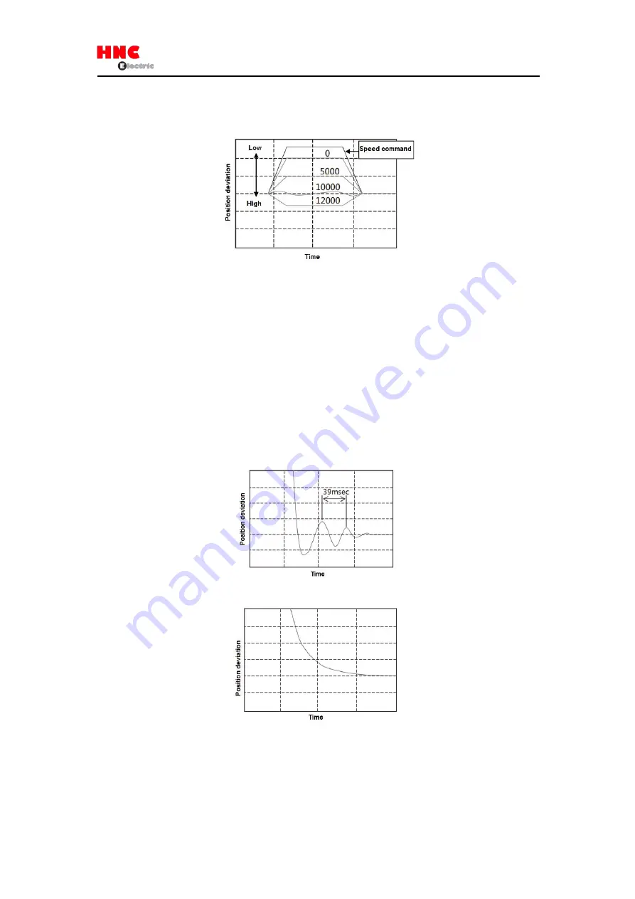
Figure 8.8.6 Position deviation convergence difference set by Gain FF compensation 2
8.8.3 Vibration reduction adjustment
①
Vibration reduction methods for smoothing filter
The adjustment method for [Position command smoothing filter 1(No.66.0)] and [Position command smoothing filter 1 Moving
average order(No.80.0)] are shown below.
Set the [Position command smoothing filter 1(No.66.0)] to “1” and set the [Position command smoothing filter 1 Moving
average order(No.80.0)] to the value calculated by the cycle time of vibration. The bigger the value is, the longer the command
delay time is.
Formula: Parameter No.80.0 setting value=Vibration cycle time [s] ×6, 250
(
750W or less
)
Parameter No.80.0 setting value=Vibration cycle time [s] ×5, 000
(
1Kw or more
)
In this example, the vibration cycle time is 39ms, and the average order is 6250
×
0. 039
=
243.
The delay tie is 243
×
0. 16ms
=
38. 88ms.
Figure 8.8.7 Before Position command smoothing filter 1 setting
Figure 8.8.8 After Position command smoothing filter 1 setting
②
Vibration reduction methods for notch filter
The adjustment method for torque command notch filter No.160.1, 168. 0
、
169. 0
.
170. 0 are shown below. Set the [Torque
command Selection of whether to use notch filter(No.160.1)] to “1” and set the vibration frequency in the [Torque command
Notch filter frequency(No.168.0)]. The vibration frequency is calculated from the waveform such as the torque command when
Summary of Contents for SV-E3 Series
Page 21: ...21 ...
Page 25: ...25 ...
Page 27: ...27 ...
Page 28: ...28 ...
Page 29: ...29 ...
Page 30: ...30 3 5 Dimensions of servo drive Same dimensions for SV E3 ...
Page 41: ...41 Figure 5 3 1 ...


