159
Table 9.3.1
Cause
What to do
The user I/O connector is not connected to 24V
DC.
Connecting 24V DC to the user I/O connector.
Pin1 and 3 is connected to 24V DC. Pin2 and 12 is connected to GND.
The user I/O connector loosens.
Check the connection and make sure it’s OK.
24V DC voltage drops.
Check the capacity of 24V DC.
Drive itself failure.
Consult with CCSERVO Corporation.
■
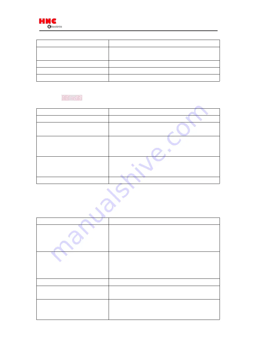
Troubleshooting 2 (Servo not ON)
Even though
「
」
is displayed on the setting panel, the servo cannot start.
Table 9.3.2
Cause
What to do
There is no servo ON(SVON) signal input.
Input SVON signal of host control device to the user I/O connector.
Alarm No.15 occurs.
There is no 200V AC input.
Make sure CHARGE LED is ON. If not, check if the 200V AC input
connector(L1/L2) is loosen or the 200V AC is output or not.
Alarm No.15 occurs.
There is no main circuit power input in
multi-axial drive.
Connect the main circuit power supply.
The motor power output connector (U/V/W)
loosen.
Check the connection and make sure it’s OK.
Make sure if it’s connected in accordance with the connector installing
method in the user’s manual.
Drive itself failure.
Consult HCFA Corporation distributor
■
Troubleshooting 3 (Motor cannot rotate)
The servo is ON, but the motor will not operate.
Table 9.3.3
Cause
What to do
Wrong parameter setting.
For setting all the basic parameters in all control modes, refer to chapter 8
「
Table 8.2.4, Table 8.3.2, Table 8.4.2 and Table 8.5.2
」
.For position control
mode and internal position command mode, refer to
「
Appendix 2 SV-E3
Positioner function
」
.
The connection of user I/O connector is not
correct.
For correct connection, refer to
「
Figure 8.2.1, Figure 8.2.2, Figure 8.2.3,
Figure 8.3.1, Figure8.4.1 and Figure 8.5.1
」
. .For position control mode and
internal position command mode, refer to
「
Appendix 2 SV-E3 Positioner
function
」
.
Command input is restricted.
Disconnect the HOLD and COM- of user I/O connector.
Torque command limit setting is not correct.
Set parameter No.147.0 and 148.0 correctly when using torque command
limit.
CCW/CW drive restriction input becomes
effective.
Set the parameter No.67.0 to
「
0
」
when not using CCW/CW drive
restriction input. CCWL, CWL and COM- of user I/O connector should be
closed when using CCW/CW drive restriction input.
Summary of Contents for SV-E3 Series
Page 21: ...21 ...
Page 25: ...25 ...
Page 27: ...27 ...
Page 28: ...28 ...
Page 29: ...29 ...
Page 30: ...30 3 5 Dimensions of servo drive Same dimensions for SV E3 ...
Page 41: ...41 Figure 5 3 1 ...


