GE
D
IRECTION
5573152-100, R
EV
. 2
LOGIQ E9 S
ERVICE
M
ANUAL
Chapter 8 Replacement procedures
8 - 221
8-9-4-1
BEP Side I/O Board - BEP6.x removal
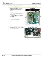
Table 8-136 BEP Side I/O Board - BEP6.x removal
Steps
Corresponding Graphic
1.
Disconnect all I/O cables and all cables at the top of the BEP. See:
connectors - J5 PCIe to GFI2 is present on GFI Configuration" on page 8-208
.
2.
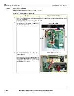
Loosen the thumb screws or screws at the top of the BEP cover, or the three screws that attach
the cover to the BEP.
Tilt the top of the BEP cover away from the BEP.
3.
Disconnect:
• the battery cable from
PCN1
.
• the CB to PB cable from
PCN2
.
Place the BEP cover aside.
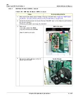
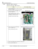
BEP6 CB cables
4.
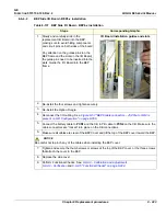
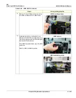
Remove the Option Dongle, on the I/O
Board, inside the BEP.
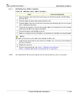
Option Dongle
Summary of Contents for LOGIQ E9
Page 2: ......
Page 11: ...GE DIRECTION 5573152 100 REV 2 LOGIQ E9 SERVICE MANUAL xi ZH CN KO ...
Page 753: ......
Page 754: ......

