GE
D
IRECTION
5573152-100, R
EV
. 2
LOGIQ E9 S
ERVICE
M
ANUAL
Chapter 8 Replacement procedures
8 - 301
8-12-4
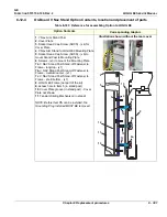
On-Board V Nav Stand Option Contents, location and placement of parts
Table 8-185 Reference for assembling Option to LOGIQ E9
Option Contents
Corresponding Graphic
1
. V Nav Arm Stand Post
2
. Cover Plate
3
. Socket Head Cap Screw (SHCS) - (x4) for
Cover Plate
4
. V Nav Arm Stand to LOGIQ E9 Mounting Plate
5
. Socket Head Cap Screw (SHCS) - (x6) to
mount Stand Post to Mounting Plate
6
. Screws - (x3) to mount the Mounting Plate
7a
. V NAV Stand Post Stand-off Fastener to
Frame - long/top - (x1)
7b
. V NAV Stand Post Stand-off Fastener to
Frame - medium/center - (x1)
7c
. V NAV Stand Post Stand-off Fastener to
Frame - short/bottom - (x1)
8
. LOGIQ E9 Frame (not part of the kit)
9
. access hole to Item 5 (in stand post)
10
. Cover Plate groove (in stand post) - Cover
Plate not shown
11
. Tension/Sliding Mechanism (in stand)
NOTE: Before Item
7b
can be installed, the
Grounding Plug installed MUST BE removed.
Illustration shown without the rear cover
1
2
3
4
5
6
7a
8a
10
11
12
9
8a
8b
7b
7c
13
Summary of Contents for LOGIQ E9
Page 2: ......
Page 11: ...GE DIRECTION 5573152 100 REV 2 LOGIQ E9 SERVICE MANUAL xi ZH CN KO ...
Page 753: ......
Page 754: ......

