GE
D
IRECTION
5573152-100, R
EV
. 2
LOGIQ E9 S
ERVICE
M
ANUAL
Chapter 7 Diagnostics/Troubleshooting
7 - 51
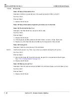
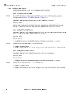
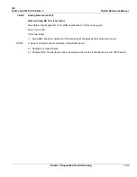
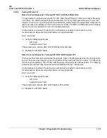
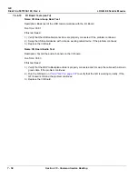
Name: Service Diagnostics / Analog CW / GRX aCW Post Mixer Gain
For each subtest, a signal is set up with f0=2.521 MHz, the BP filter at 3.1 MHz and a mixer frequency
of 2.5 MHz. The dither and Pedof inputs are disabled. The TSIG_GAIN parameter is set to give -26.1
dB gain. The test is run by setting up the four different IQ_GAIN parameter settings that corresponds to
the 4 post mixer gain setting of 0 dB, -4 dB, -8 dB and -12 dB. The RMS and RMS attenuation between
the four mixers gain settings on both I- and Q-data are tested.
Are the probes connected? The test will run with probes connected to the scanner, but it is
recommended to disconnect all probes before running diagnostics.
Run Time: 00:05
1.) Verify the following tests pass:
-
GFI Tests
-
Analog Receive Tests
If these tests pass, and the GRX aCW Post Mixer Gain test fails:
2.) Replace the CW GRX board.
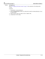
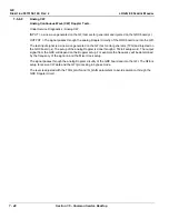
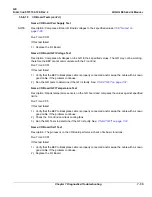
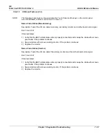
Name: Service Diagnostics / Analog CW / GRX aCW Doppler LPF
For the Low Pass Filter test, Doppler test frequencies, both in the filter pass band and the stop band are
set up. The mixer clock frequency is set to 2.5 MHz and the band pass filter to 3.1 MHz. The dither and
Pedof inputs are disabled. The LP-filter 3 dB frequency will typically be at about 40 kHz. The following
parameters are tested: fdop, spectrum peak and RMS both in the I- and Q-data.
Are the probes connected? The test will run with probes connected to the scanner, but it is
recommended to disconnect all probes before running diagnostics.
Run Time: 00:05
1.) Verify the following tests pass:
-
GFI Tests
-
Analog Receive Tests
If these tests pass, and the GRX aCW Doppler LPF test fails:
2.) Replace the CW GRX board.
Summary of Contents for LOGIQ E9
Page 2: ......
Page 11: ...GE DIRECTION 5573152 100 REV 2 LOGIQ E9 SERVICE MANUAL xi ZH CN KO ...
Page 753: ......
Page 754: ......


