GE
D
IRECTION
5573152-100, R
EV
. 2
LOGIQ E9 S
ERVICE
M
ANUAL
Chapter 8 Replacement procedures
8 - 109
8-6-3-1
LCD Arm (Original) replacement - R3.x and earlier
Table 8-70 LCD Arm assembly (Original) removal
Steps
Corresponding Graphic
1.
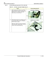
Disconnect the LCD cables; video (
P10
)
and power (
P3
) from the connectors on the
Bulkhead. The Gel Warmer cable (
P1
)
does not have to be removed.
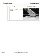
LCD Cables at Bulkhead
2.
Push the LCD Mount Lock handle (
1
) into
the unlocked position (shown LOCKED).
DO NOT loosen nut (
2
).
Move the LCD Arm from side to side when
at the same time pulling upwards, until you
can lift LCD Arm assembly away.
LCD Mount Lock Handle
Summary of Contents for LOGIQ E9
Page 2: ......
Page 11: ...GE DIRECTION 5573152 100 REV 2 LOGIQ E9 SERVICE MANUAL xi ZH CN KO ...
Page 753: ......
Page 754: ......


