GE
D
IRECTION
5573152-100, R
EV
. 2
LOGIQ E9 S
ERVICE
M
ANUAL
Chapter 8 Replacement procedures
8 - 279
8-11-8-2
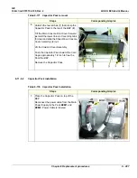
Printer Bracket installation
Table 8-173 Printer Bracket installation
Steps
Corresponding Graphic
1.
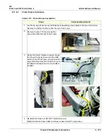
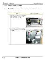
Cut the tie wrap that secures the Drive Gear Assembly power cable to the top of the Frame.
Remove the Cable Tie Mount from the top of the Frame.
2.
Remove the two T30 torx screws that
secure the Z-Mechanism to the Frame.
3.
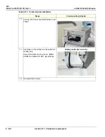
Route the Printer Cables as shown. Route
the Power Cable as shown and the USB
Cable on top of the Frame, along the inside
edge of the Rear Handle. Continue to route
the USB Cable inside the Frame to
J26
on
the BEP.
4.
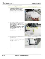
Re-install the Rear, but DO NOT install the screws.
MAKE SURE the Printer USB and Power Cables DO NOT get pinched.
Summary of Contents for LOGIQ E9
Page 2: ......
Page 11: ...GE DIRECTION 5573152 100 REV 2 LOGIQ E9 SERVICE MANUAL xi ZH CN KO ...
Page 753: ......
Page 754: ......


