GE
D
IRECTION
5573152-100, R
EV
. 2
LOGIQ E9 S
ERVICE
M
ANUAL
8 - 306
Section 8-12 - V Nav Roll Stand and/or On-Board Stand Installation and/or Replacement
8-12-6
Adjusting Tension on Sliding Mechanism
9.
Mount the transmitter and tighten the
transmitter mounting screws (
A
) on the arm
and route the cable through the cable
management channels (
B
), in the under-
side of the arms. The arm is showed in the
stowed position.
While supporting the arm (loaded with the
transmitter), slowly loosen the knob which
allows the arm to gradually move down the
channel.
NOTE: The arm must move down the
channel very slowly when the knob is
loosened, and it must move easily upward
when lifting. If the arm free-falls or will not
move, follow the adjustment procedure,
see:
8-12-6 "Adjusting Tension on Sliding
.
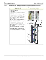
Table 8-187 Adjusting Tension on Sliding Mechanism
Steps
Corresponding Graphic
1.
Remove the plastic bolt cap from the lower
tension nut.
The clamping knob must be unlocked while
making this adjustment. Using the 1/2 inch
socket wrench, loosen or tighten the
tension nut for the desired tension.
Plastic Bolt Cap for tension nut and Unlocking
Clamping Knob
2.
Perform Functional Checks. See:
8-12-6-1 - Calibration and adjustments
and
8-12-6-3 "Functional Checks" on page 8-307
.
Table 8-186 Option Installation to LOGIQ E9
Steps
Corresponding Graphic
Summary of Contents for LOGIQ E9
Page 2: ......
Page 11: ...GE DIRECTION 5573152 100 REV 2 LOGIQ E9 SERVICE MANUAL xi ZH CN KO ...
Page 753: ......
Page 754: ......


