GE
D
IRECTION
5573152-100, R
EV
. 2
LOGIQ E9 S
ERVICE
M
ANUAL
8 - 208
Section 8-9 - BEP (Back End Processor) parts replacement
8-9-2
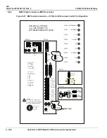
BEP6 Cable Connectors (BEP Door Label)
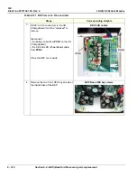
Figure 8-57 BEP6 cable connectors - J5 PCIe to GFI2 is present on GFI Configuration
3
4
6
5
1
2
3
4
6
5
1
2
!
3
4
1
2
6
5
J100 Op
Panel Video
J7 Op Panel
Buttons
J28 4D
Motorcontroller
J27 DriveBay
J26 BW
Printer
J25 XYZ
Motorcontroller
J2 SA2
DVD
J3 SA1
SPARE
J4 Main
PS USB
J46 LAN
10/100/1000
t
u
O
o
e
di
V
r
e
m
ot
s
u
C
4
4J
J41 Customer USB
J40 Customer USB
Customer Audio
J43
J42
t
u
O
o
e
di
V
D
CL
r
e
p
p
U
1
2J
t
u
O
V/
A
2
2J
r
ot
c
e
n
n
o
C
ts
eT
J33 Center
Power Power
J29
Power
J30
Power
WARNING:
J29-30 are for powering peripheral
devices. They are not keyboard/mouse
ports and will destroy any keyboard or
mouse that is plugged into them.
Test Connector
pins of note:
5, 13, 23 - Ground
3 - 24V
4 - 48V
8 - 12V
9 - 5V
10 - AC_FAIL_N
11 - 3.3V
12 - 5V_STDBY
16 - VBAT_TP
24 - PWR_SW
25 - PSON_N
Power Pinout:
1, 2 - GND
3,5 - 12V
4,6 - 5V
J22 pins of note:
5 - PWR_SW
6 - 5V_STDBY
9-13 - 48V
17, 21-25 - GND
18 - PWR_LED_P
BEP Rear
BEP Face
REMOVE ALL OPTIONS
(e.g. DVR, PATIENT I/O)
BEFORE RETURNING TO SWAP
13
13
14
1
14
25
25
1
J14 Spare
3
4
1
2
J45
Customer
S-Video
J12 Options
Dongle
Inside BEP
PLED2 ATX POWER OK
PLED3 POWER ON
PLED4 +3.3V
PLED2 +48V
PLED7 POWER OK
PLED1 +5V
PLED6 +28V
PLED5 +5V STBY
PLED2 +12V
BEP Front
J9 Customer USB
J8 Customer USB
SPD LED
ACT LED
ACT LED
J1 Main PS
48V, 5V In
BEP Top
J5 PCIe
to GFI2
(legacy)
Inside BEP
On/
Off
Reset
R4 only
Summary of Contents for LOGIQ E9
Page 2: ......
Page 11: ...GE DIRECTION 5573152 100 REV 2 LOGIQ E9 SERVICE MANUAL xi ZH CN KO ...
Page 753: ......
Page 754: ......

