3
1.1 Names and Functions of Parts
1
NA
ME
S AND FUNCTIONS OF P
A
R
T
S
■
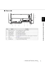
Rear side
No.
Name
Function
1
Main power switch
For switching the power supply ON/OFF.
2
Power connector
For connecting the AC cable.
3
SCSI ID Switch
Sets the scanner’s SCSI ID.
4
SCSI connector
For connecting the SCSI cable.
5
USB connector
For connecting the USB cable.
6
Extended memory
slot
For connecting an extension memory (sold separately). For details see
section 9.4
.
7
VRS slot
The VRS board has been installed in this slot.
8
Extended slot
A spare slot for a third party board
1
2
3
4
5
6
7
8
Summary of Contents for NSS8 and NSS12
Page 2: ......
Page 20: ...xviii ...
Page 114: ...94 3 9 Multi Image Output 6 Click the Scan button to scan the document ...
Page 118: ...98 3 10 Color monochrome Auto Detection ...
Page 134: ...114 4 5 Cleaning the Transport path and the sensors ...
Page 184: ...164 7 8 Scanning Mixed Documents ...
Page 214: ...194 8 17 Timeout for Manual Feeding ...
Page 225: ...205 10 3 Dimensions 10 SCANNER SPECIFICATIONS 10 3 Dimensions unit mm ...
Page 226: ...206 10 3 Dimensions ...
Page 229: ...IN 3 ...

