


Maintenance
General Information
4
4-11
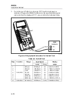
To disassemble the microcomputer pcb, use the following procedure:
1.
Turn the main pcb face down and remove the two small screws at the
top of the pcb to free the microcomputer pcb.
2.
Refer to Figure 4-2. Beginning with item 7, remove items 7 through 3
(leave item 2 attached to item 1). Be sure to observe the handling
precautions for items 7, 5, and 4.
To assemble the microcomputer LCD, refer to Figure 4-2. Beginning with
item 3, assemble items 3 through 7 (in ascending numerical order). Be sure
to follow the handling precautions for items 4, 5, and 7.
4-9.
Backup Fuse Replacement
Use the following procedure to replace the backup fuse (F2):
1.
Remove the top cover by following the precautions given previously for
the calibration and backup fuse access.
2.
Use a flat-tipped screwdriver to pry the fuse out of its fuse holder. Pry
the fuse from the side as indicated in Figure 4-1.
3.
Replace the defective backup fuse with a 3A/600V type BBS-3 (Fluke
PN 475004). Refer to section 2-4 for information about replacing fuse
F1 (2A/250V; American style: fast acting type AGX2 1/4 x 1”, Fluke
PN 376582; European style: 5 x 20 mm, Fluke PN 460972).
4-10. Cleaning
Clean the front panel and case with a damp cloth and mild detergent. Do not
use abrasives, solvents, or alcohol.
Warning
To avoid electrical shock, remove test leads and any
input signals before cleaning.
Summary of Contents for 8062A
Page 4: ......
Page 8: ...8062A Instruction Manual iv...
Page 10: ...8062A Instruction Manual vi...
Page 14: ...8062A Instruction Manual 1 2...
Page 24: ...8062A Instruction Manual 2 2...
Page 50: ...8062A Instruction Manual 2 28...
Page 52: ...8062A Instruction Manual 3 2...
Page 62: ...8062A Instruction Manual 3 12...
Page 64: ...8062A Instruction Manual 4 2...
Page 90: ...8062A Instruction Manual 4 28...
Page 92: ...8062A Instruction Manual 5 2...
Page 102: ...8062A Instruction Manual 5 12 8062A 4031 iv39c eps Figure 5 2 A1 Main PCB Assembly...
Page 106: ...8062A Instruction Manual 6 2...
Page 108: ...8062A Instruction Manual 6 4 dy55c eps Figure 6 1 Accessories...
Page 118: ...8062A Instruction Manual 7 2...
Page 122: ...8062A Instruction Manual 7 6...
Page 123: ...8062A Instruction Manual 7 7 8062A 1201 iu46c eps Figure 7 5 A1 Main PCB Schmatic Diagram...
Page 124: ...8062A Instruction Manual 7 8 8060A 1003 iu61f eps Figure 7 6 A3 RMS PCB Schmatic Diagram...


