8062A
Instruction Manual
4-6
Note
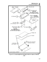
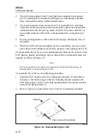
It is not necessary to remove the main pcb from the bottom case in
order to disassemble or reassemble the LCD. However, because the
LCD and the microcomputer require similar special handling, the
disassembly and reassembly procedures are described together.
Caution
To avoid contaminating the pcbs with oil from the
fingers, handle the pcbs by the edges or wear gloves.
4-6.
Calibration and Backup Fuse Access
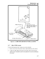
Use the following procedure to gain access to the calibration adjustments or
the backup fuse (F2):
1.
Disconnect the test leads and battery eliminator, if attached. Turn the
power switch off.
2.
Remove the three phillips screws from the bottom of the case.
3.
Turn the instrument face-up and grasp the top cover at both sides of the
input connectors. Then pull the top cover from the unit. The backup fuse
and the calibration adjustments are now accessible (Figure 4-1).
Caution
The function buttons below the display are part of a
single elastomeric strip (Figure 4-1) that is held in place
by the top cover. When the top cover is removed, the
elastomeric strip will be loose and may be removed. Do
not touch or contaminate the carbon-impregnated switch
contacts on the bottom of the strip or the switch
contacts on the microcomputer pcb. If the contacts do
become contaminated, clean them with isopropyl
alcohol.
4.
To reassemble, position the elastomeric strip on the microcomputer pcb
so that the small rubber posts on the bottom of the strip are properly
seated. Install the top cover and fasten the three screws on the bottom
case.
Summary of Contents for 8062A
Page 4: ......
Page 8: ...8062A Instruction Manual iv...
Page 10: ...8062A Instruction Manual vi...
Page 14: ...8062A Instruction Manual 1 2...
Page 24: ...8062A Instruction Manual 2 2...
Page 50: ...8062A Instruction Manual 2 28...
Page 52: ...8062A Instruction Manual 3 2...
Page 62: ...8062A Instruction Manual 3 12...
Page 64: ...8062A Instruction Manual 4 2...
Page 90: ...8062A Instruction Manual 4 28...
Page 92: ...8062A Instruction Manual 5 2...
Page 102: ...8062A Instruction Manual 5 12 8062A 4031 iv39c eps Figure 5 2 A1 Main PCB Assembly...
Page 106: ...8062A Instruction Manual 6 2...
Page 108: ...8062A Instruction Manual 6 4 dy55c eps Figure 6 1 Accessories...
Page 118: ...8062A Instruction Manual 7 2...
Page 122: ...8062A Instruction Manual 7 6...
Page 123: ...8062A Instruction Manual 7 7 8062A 1201 iu46c eps Figure 7 5 A1 Main PCB Schmatic Diagram...
Page 124: ...8062A Instruction Manual 7 8 8060A 1003 iu61f eps Figure 7 6 A3 RMS PCB Schmatic Diagram...

