


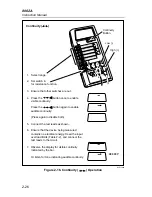


Theory of Operation
Introduction
3
3-3
3-1. Introduction
This chapter describes how the 8062A works. An overview of the operation
is provided first, followed by description of the two major components and
the measurement functions. A detailed schematic of the instrument appears in
Chapter 7.
3-2. Functional
Description
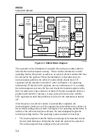
The major circuits and components of the 8062A are arranged in a block
diagram in Figure 3-1. Two major components make up the measurement
system: a four-bit CMOS microcomputer, and CMOS integrated circuit
known as the Measurement Acquisition Chip (MAC). The microcomputer
selects the appropriate measurement function in the MAC according to the
switches or buttons pushed by the operator. The microcomputer also controls
the measurement cycles, performs calculations on measured data, and drives
the display. The MAC measures the conditioned input signals with the a/d
converter or the frequency counter. The MAC also controls the power supply
and the continuity tone generator. The microcomputer and the MAC
communicate through a four-bit bidirectional bus and four control lines. Both
components are described in more detail later in this chapter.
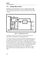
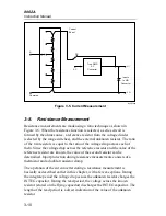
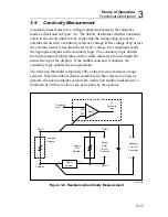
As shown in Figure 3-1, the input signals are routed by the range and
function switches through the appropriate signal conditioners for input
filtering and scale changes. Input signals for all measurement functions
except frequency are converted to a proportional dc analog voltage that is
applied to the a/d converter. The dual-slope a/d converter converts the dc
analog voltage to a digital number that is sent to the microcomputer. Each of
the major measurement functions are described later in this chapter.
3-3. Microcomputer
The four-bit CMOS microcomputer senses switch positions by reading status
registers in the MAC, and senses button pushes through input lines connected
directly to the microcomputer. The microcomputer processes the information
and then selects the appropriate digital and analog configuration in the MAC
by writing to an array of MAC control registers.
Summary of Contents for 8062A
Page 4: ......
Page 8: ...8062A Instruction Manual iv...
Page 10: ...8062A Instruction Manual vi...
Page 14: ...8062A Instruction Manual 1 2...
Page 24: ...8062A Instruction Manual 2 2...
Page 50: ...8062A Instruction Manual 2 28...
Page 52: ...8062A Instruction Manual 3 2...
Page 62: ...8062A Instruction Manual 3 12...
Page 64: ...8062A Instruction Manual 4 2...
Page 90: ...8062A Instruction Manual 4 28...
Page 92: ...8062A Instruction Manual 5 2...
Page 102: ...8062A Instruction Manual 5 12 8062A 4031 iv39c eps Figure 5 2 A1 Main PCB Assembly...
Page 106: ...8062A Instruction Manual 6 2...
Page 108: ...8062A Instruction Manual 6 4 dy55c eps Figure 6 1 Accessories...
Page 118: ...8062A Instruction Manual 7 2...
Page 122: ...8062A Instruction Manual 7 6...
Page 123: ...8062A Instruction Manual 7 7 8062A 1201 iu46c eps Figure 7 5 A1 Main PCB Schmatic Diagram...
Page 124: ...8062A Instruction Manual 7 8 8060A 1003 iu61f eps Figure 7 6 A3 RMS PCB Schmatic Diagram...


