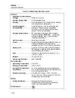


8062A
Instruction Manual
2-14
Since average-responding meters have been in use for so long, you may have
accumulated test or reference data based on them. The conversion factors in
Figure 2-8 should help you convert between the two measurement methods.
2-15. High Impedance DC Voltage
Occasionally you may want to make dc voltage measurements in high
impedance circuitry where even the 10 M
Ω
input impedance for the normal
dc voltage function could load the circuit and cause significant errors. For
example, a 10 M
Ω
input impedance causes a .1% error when measuring the
voltage across the 10 k
Ω
leg of a 90 k
Ω
over 10 k
Ω
voltage divider. The
8062A offers a >1000 M
Ω
(typically >10,000 M
Ω
) input impedance dc
voltage function which greatly reduces this error.
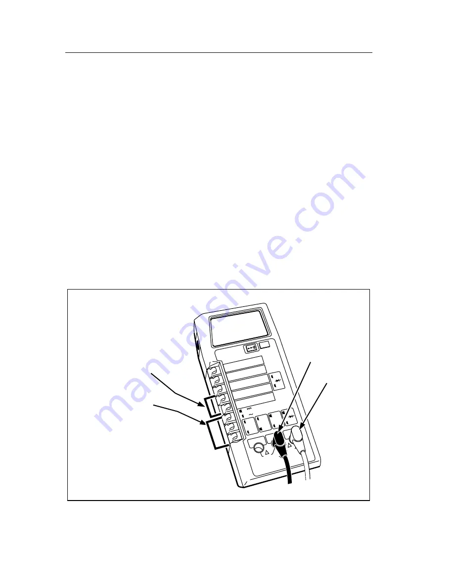
Figure 2-9 describes how to select the high input impedance dc voltage
function (the ac voltage function does not operate in this mode). Notice that
all of the function switches must be out to select this function. Either the 2V
or the 200 mV ranges may be selected.
2000mA
A
A
COMMON
V
Ω
S
V
Ω
S
200mA
200
200k
200
µ
A
DC
AC
200mV
200
Ω
20mA
20
20k
2mA
2
2k
1000 DC
750 AC
M
Ω
REL
1000V DC
750V AC
MAX
2A MAX
500V MAX
!
!
Low (-)
High Impedance
DC Voltage (V)
High (+)
1. Select the 2V or
the 200 mV range.
2. Ensure all function
switches are out.
3. Connect the test leads as shown.
4. Heed the input overload limits
(Table 2-2) and connect the leads to
the circuit being measured.
5. Read the measured value on the display.
dy10f.eps
Figure 2-9. High Impedance DC Voltage
Summary of Contents for 8062A
Page 4: ......
Page 8: ...8062A Instruction Manual iv...
Page 10: ...8062A Instruction Manual vi...
Page 14: ...8062A Instruction Manual 1 2...
Page 24: ...8062A Instruction Manual 2 2...
Page 50: ...8062A Instruction Manual 2 28...
Page 52: ...8062A Instruction Manual 3 2...
Page 62: ...8062A Instruction Manual 3 12...
Page 64: ...8062A Instruction Manual 4 2...
Page 90: ...8062A Instruction Manual 4 28...
Page 92: ...8062A Instruction Manual 5 2...
Page 102: ...8062A Instruction Manual 5 12 8062A 4031 iv39c eps Figure 5 2 A1 Main PCB Assembly...
Page 106: ...8062A Instruction Manual 6 2...
Page 108: ...8062A Instruction Manual 6 4 dy55c eps Figure 6 1 Accessories...
Page 118: ...8062A Instruction Manual 7 2...
Page 122: ...8062A Instruction Manual 7 6...
Page 123: ...8062A Instruction Manual 7 7 8062A 1201 iu46c eps Figure 7 5 A1 Main PCB Schmatic Diagram...
Page 124: ...8062A Instruction Manual 7 8 8060A 1003 iu61f eps Figure 7 6 A3 RMS PCB Schmatic Diagram...


