


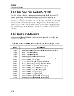


Accessory Information
High Voltage Probe (80K-40)
6
6-7
6-6. High Voltage Probe (80K-40)
The Model 80K-40 extends the voltage measurement capability of the
instrument up to 40 kV. Internally, the probe contains a special 1000:1
resistive divider. Metal-film resistors with matched temperature coefficients
comprise the divider, and provide the probe with its excellent accuracy and
stability characteristics. Also, an unusually high input impedance (1000 M
Ω
)
minimizes circuit loading, and thereby contributes to measurement accuracy.
VOLTAGE RANGE .........................
1 kV to 40 kV dc or peak ac, 28 kV
rms ac
INPUT RESISTANCE......................
1000 M
Ω
DIVISION RATIO............................
1000:1
ACCURACY DC (OVERALL) ........
20 kV to 30 kV
±
2% (calibrated at
25 kV)
UPPER LIMIT ..................................
Changes linearly from 2% at 30 kV
to 4% at 40 kV
LOWER LIMIT ................................
Changes linearly from 2% at 20 kV
to 4% at 1 kV
ACCURACY AC (OVERALL) ........
±
5% at 60 Hz
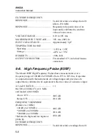
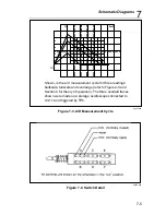
6-7. High Frequency Probe (83RF)
The 83RF Probe extends the frequency range of your multimeter’s voltage
measurement capability to include 100 kHz to 100 MHz inputs from 0.25 to
30V rms. The probe operates in conjunction with the instrument’s dc voltage
ranges, and provides a dc output that is calibrated to be equivalent to the rms
value of a sinewave input.
AC-to-DC RATIO.............................
1:1
RATIO ACCURACY (At 1 MHz
and loaded with 10 M
Ω
)
Above 1V ........................................
Below 1V ........................................
±
1 dB
±
1.5 dB
FREQUENCY RESPONSE
(Relative to 1 MHz)
100 kHz to 100 MHz.........................
±
1 dB
Summary of Contents for 8062A
Page 4: ......
Page 8: ...8062A Instruction Manual iv...
Page 10: ...8062A Instruction Manual vi...
Page 14: ...8062A Instruction Manual 1 2...
Page 24: ...8062A Instruction Manual 2 2...
Page 50: ...8062A Instruction Manual 2 28...
Page 52: ...8062A Instruction Manual 3 2...
Page 62: ...8062A Instruction Manual 3 12...
Page 64: ...8062A Instruction Manual 4 2...
Page 90: ...8062A Instruction Manual 4 28...
Page 92: ...8062A Instruction Manual 5 2...
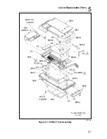
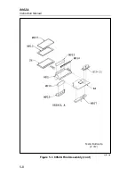
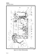
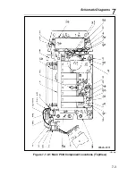
Page 102: ...8062A Instruction Manual 5 12 8062A 4031 iv39c eps Figure 5 2 A1 Main PCB Assembly...
Page 106: ...8062A Instruction Manual 6 2...
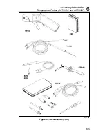
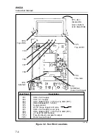
Page 108: ...8062A Instruction Manual 6 4 dy55c eps Figure 6 1 Accessories...
Page 118: ...8062A Instruction Manual 7 2...
Page 122: ...8062A Instruction Manual 7 6...
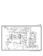
Page 123: ...8062A Instruction Manual 7 7 8062A 1201 iu46c eps Figure 7 5 A1 Main PCB Schmatic Diagram...
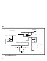
Page 124: ...8062A Instruction Manual 7 8 8060A 1003 iu61f eps Figure 7 6 A3 RMS PCB Schmatic Diagram...


