


vii
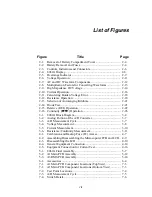
List of Figures
Figure
Title
Page
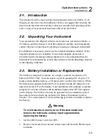
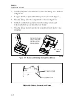
2-1.
Removal of Battery Compartment Cover ................................. 2-4
2-2.
Battery Removal and Fuses...................................................... 2-4
2-3.
Controls, Indicators and Connectors........................................ 2-6
2-4.
8062A Display ......................................................................... 2-8
2-5.
Overrange Indicator ................................................................. 2-9
2-6.
Voltage Operation.................................................................... 2-11
2-7.
AC and DC Waveform Components........................................ 2-12
2-8.
Multiplication Factors for Converting Waveforms .................. 2-13
2-9.
High Impedance DC Voltage ................................................... 2-14
2-10. Current Operation .................................................................... 2-16
2-11. Calculating Burden Voltage Error ........................................... 2-18
2-12. Resistance Operation ............................................................... 2-18
2-13. Selection of Autoranging Kilohms........................................... 2-21
2-14. Diode Test................................................................................ 2-21
2-15. Relative (REL) Operation ........................................................ 2-22
2-16. Continuity (
) Operation .................................................. 2-26
3-1.
8062A Block Diagram ............................................................. 3-4
3-2.
Analog Portion of the A/D Converter ...................................... 3-7
3-3.
A/D Measurement Cycle.......................................................... 3-7
3-4.
Voltage Measurement .............................................................. 3-8
3-5.
Current Measurement............................................................... 3-10
3-6.
Resistance/Continuity Measurement........................................ 3-11
4-1.
Calibration and Backup Fuse (F2) Access ............................... 4-7
4-2.
Assembling/Disassembling the Microcoputer PCB and LCD.. 4-9
4-3.
Disassembling the LCD ........................................................... 4-10
4-4.
General Equipment Connection ............................................... 4-14
4-5.
Equipment Connection for Current Test .................................. 4-16
5-1.
8062A Final Assembly............................................................. 5-7
5-2.
A1 Main PCB Assembly.......................................................... 5-12
5-3.
A3 RMS PCB Assembly.......................................................... 5-14
6-1.
Accessories .............................................................................. 6-4
7-1.
A1 Main PCB Component Locations (TopView).................... 7-3
7-1.
A1 Main PCB Component Locations (Bottom View) ............. 7-3
7-2.
Test Point Locations ................................................................ 7-4
7-3.
A/D Measurement Cycle.......................................................... 7-5
7-4.
Switch Detail............................................................................ 7-6
Summary of Contents for 8062A
Page 4: ......
Page 8: ...8062A Instruction Manual iv...
Page 10: ...8062A Instruction Manual vi...
Page 14: ...8062A Instruction Manual 1 2...
Page 24: ...8062A Instruction Manual 2 2...
Page 50: ...8062A Instruction Manual 2 28...
Page 52: ...8062A Instruction Manual 3 2...
Page 62: ...8062A Instruction Manual 3 12...
Page 64: ...8062A Instruction Manual 4 2...
Page 90: ...8062A Instruction Manual 4 28...
Page 92: ...8062A Instruction Manual 5 2...
Page 102: ...8062A Instruction Manual 5 12 8062A 4031 iv39c eps Figure 5 2 A1 Main PCB Assembly...
Page 106: ...8062A Instruction Manual 6 2...
Page 108: ...8062A Instruction Manual 6 4 dy55c eps Figure 6 1 Accessories...
Page 118: ...8062A Instruction Manual 7 2...
Page 122: ...8062A Instruction Manual 7 6...
Page 123: ...8062A Instruction Manual 7 7 8062A 1201 iu46c eps Figure 7 5 A1 Main PCB Schmatic Diagram...
Page 124: ...8062A Instruction Manual 7 8 8060A 1003 iu61f eps Figure 7 6 A3 RMS PCB Schmatic Diagram...


